SECTION 4: Repair
2025653-048 Revision B Responder
™
2000 Page 34
Assembly Step Details
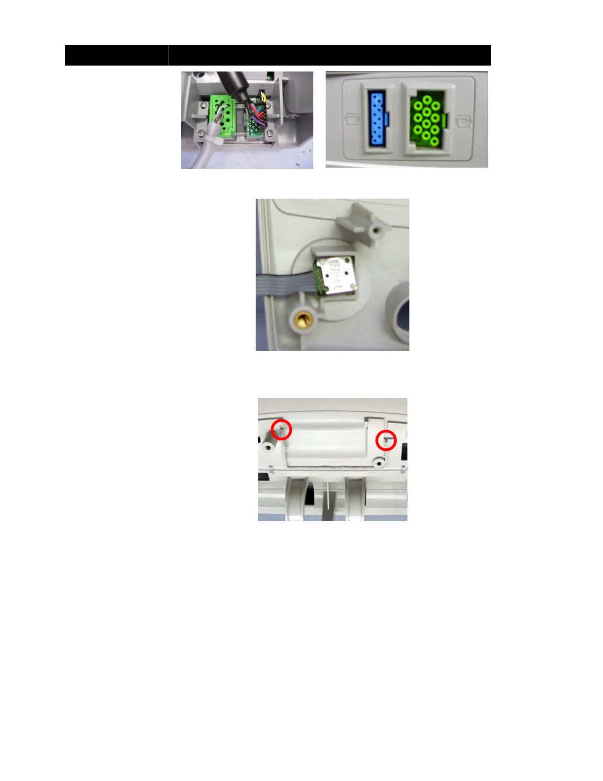
Connect the EGG cable
(and optional SPO2 cable)
to the cable cover.
Secure to the Front Body
assembly with four Phillips
screws
Note: Ensure the heart
symbol is not upside-down.
Figure 16: ECG Cable Cover
Installed
Figure 17: Correct Orientation
Insert the Rotary Selection
switch as shown.
Turn over the Front Body
assembly and place the
washer over the encoder
switch.
Tighten the nut and press
on the Rotary Selection
Knob.
Note: When properly
installed, the knob rotates
freely and clicks when
pressed.
Caution: The connection
between the encoder switch
and cable is fragile. Do not
excessively bend or twist
the cable
Figure 18: Encoder Switch
(Rear View)
Apply a 5 mm (3/16 in)
bead of silicone to seal the
joint between the Front
Body and the Lower
Frame (between the two
points as shown).
Note: The seal must be
complete (no gaps).
Figure 19: Lower Frame Silicone Application