SECTION 4: Repair
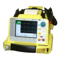
2025653-048 Revision B Responder
™
2000 Page 28
How to Replace Specific Components
Use the following procedures as a guide to replace specific internal components in the Responder 2000. Not all
components are listed. (For example, if the Front Body is damaged and must be replaced, the entire unit must be
disassembled and then reassembled using the more detailed Assembly instructions).
Capacitors (see page 46)
WARNING: Lethal Shock Hazard.
In the event of equipment failure, the two main capacitors may retain dangerous voltages even if the Responder
2000 is disconnected from AC power and the battery is removed. Normally, the capacitors are discharged when
power is shut off; however, it is possible for equipment damage to prevent the capacitors from discharging
properly.
Always assume the capacitors are fully charged.
1. Remove Rear Cover (see Figure 67: Rear Body Installed).
Note: Two cover screws are located under the Bed Hook Covers.
2. Cut tie wraps to free capacitor leads.
3. Disconnect Capacitor leads (see Figure 58: Capacitors Installed) from Therapy Board.
Caution: Equipment Damage.
Carefully note the capacitor lead connection points and double check the lead and jack labels.
Connecting the Capacitors to the wrong jack could cause equipment damage.
4. Reconnect Capacitors. Ensure lead connections are tight.
5. Tie wrap leads and cables. Refer to the assembly instructions for proper cable routing.
6. If necessary replace or reseat rubber tubing along the edge of the Front Body.
7. Replace the Rear Cover. Ensure the cover seats properly—check for gaps or bulges around the entire edge.
Note: One screw is located under the label of the Rear Cover. (See Figure 67: Rear Body Installed)
8. Replace Bed Hook Covers. Check for proper orientation (see Figure 68: Bed Hook Cover
Improperly Installed).
Therapy Board (see page 45)
1. Follow the Capacitor instructions (above) to remove the Capacitors.
2. Disconnect all other leads from the Therapy Board (see Figure 56: Therapy Board Cables Installed).
3. Remove the screws holding the Therapy Board (see Figure 54: Therapy Board Installed).
4. Exchange the board and replace screws.
5. Reconnect all cables and leads.
Caution: Equipment Damage.
Carefully note the capacitor lead connection points and double check the lead and jack labels.
Connecting the Capacitors to the wrong jack could cause equipment damage.
6. Follow the Capacitor instructions (above) to complete the reassembly.
 Loading...


