EasyManuals Logo

GE Responder 2000 Service Manual

GE Responder 2000
138 pages
To Next Page IconTo Next Page
To Previous Page IconTo Previous Page
Page #36 background imageLoading...
Page #36 background image
SECTION 4: Repair
2025653-048 Revision B Responder
2000 Page 36
Power Control Board and Power Supply Installation
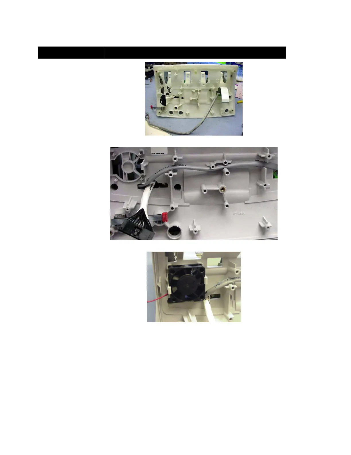
Assembly Step Details
Pass the three cables
through the holes in the
Lower Frame as shown.
Secure the Lower Frame to
the Front Body with six
Torx security screws.
Figure 21: Lower Frame (Bottom View)
Route the ECG Cable as
shown and pass it back up
into the main compartment.
Figure 22: ECG Cable Route through Lower Frame
Install the Fan.
Note: An arrow on the fan
indicates air flow direction.
Ensure the fan blows
upwards into the unit.
Figure 23: Fan Installed

Table of Contents

Other manuals for GE Responder 2000

Questions and Answers:

Question and Answer IconNeed help?

Do you have a question about the GE Responder 2000 and is the answer not in the manual?

GE Responder 2000 Specifications

General IconGeneral
BrandGE
ModelResponder 2000
CategoryMedical Equipment
LanguageEnglish

Related product manuals