SECTION 8: Specifications and Safety
2025653-048 Revision B Responder
™
2000 Page 121
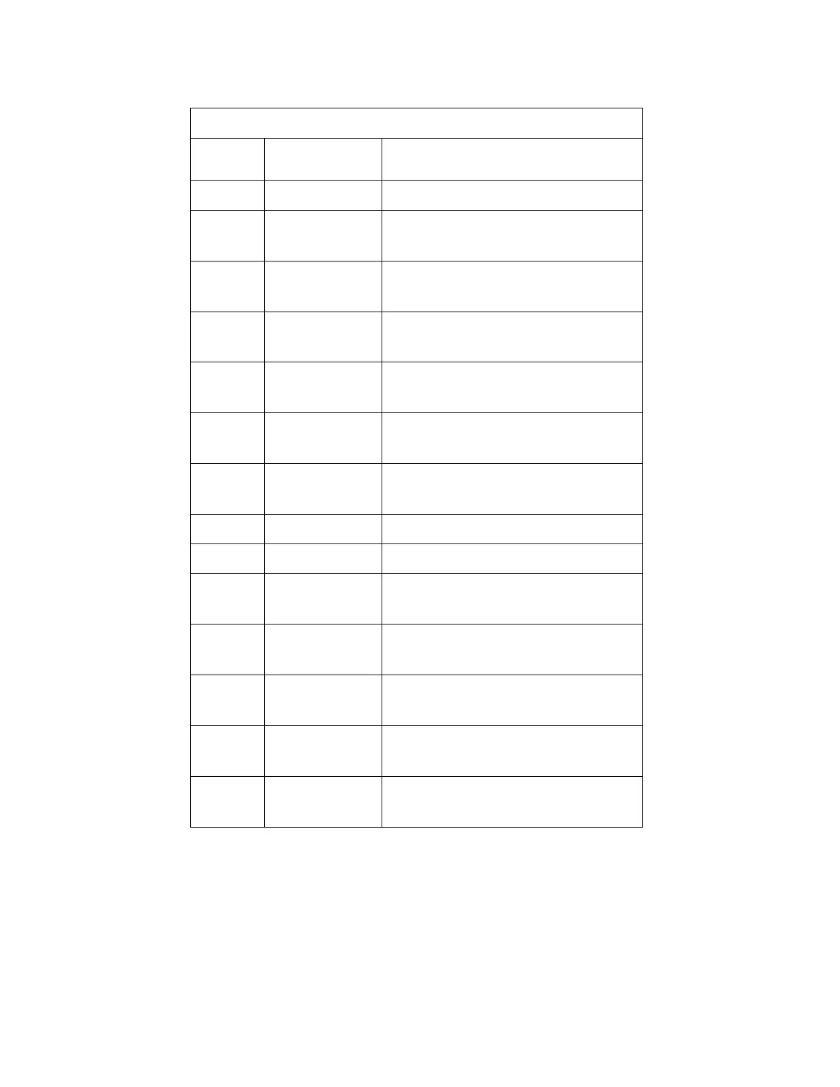
J218 – UI Interface to Power Control PCBA
(Has UI Functions)
Molex 71226-2425
Pin
Number
Name Description
1-2 GND System Ground
3 /Manual_SW Pull Down Input
Pushbutton – Manual
4 /Spare1_SW Pull Down Input
Pushbutton – Spare1
5 /Shock_SW Pull Down Input
Pushbutton – Shock
6 /Charge_SW Pull Down Input
Pushbutton – Charge
7 CPU_ADC5 Analog Input from UI/PC PCBA
Temperature Sensor
8 /Select_SW Pull Down Input
Push-knob – Trim knob Select
9 SQRB Digital Input – Trim knob phase 2
10 SQRA Digital Input – Trim knob phase 1
11 /Power_SW Pull Down Input
Pushbutton – Power
12 Power_LED LED Drive – Pull-Down Output
Power LED
13 Spare2_LED LED Drive – Pull-Down Output
Spare2 LED
14 Spare1_LED LED Drive – Pull-Down Output
Spare1 LED
15 Charge_LED LED Drive – Pull-Down Output
Charge LED