Section 5: Performance Verification and Safety Testing
2025653-048 Revision B Responder
™
2000 Page 85
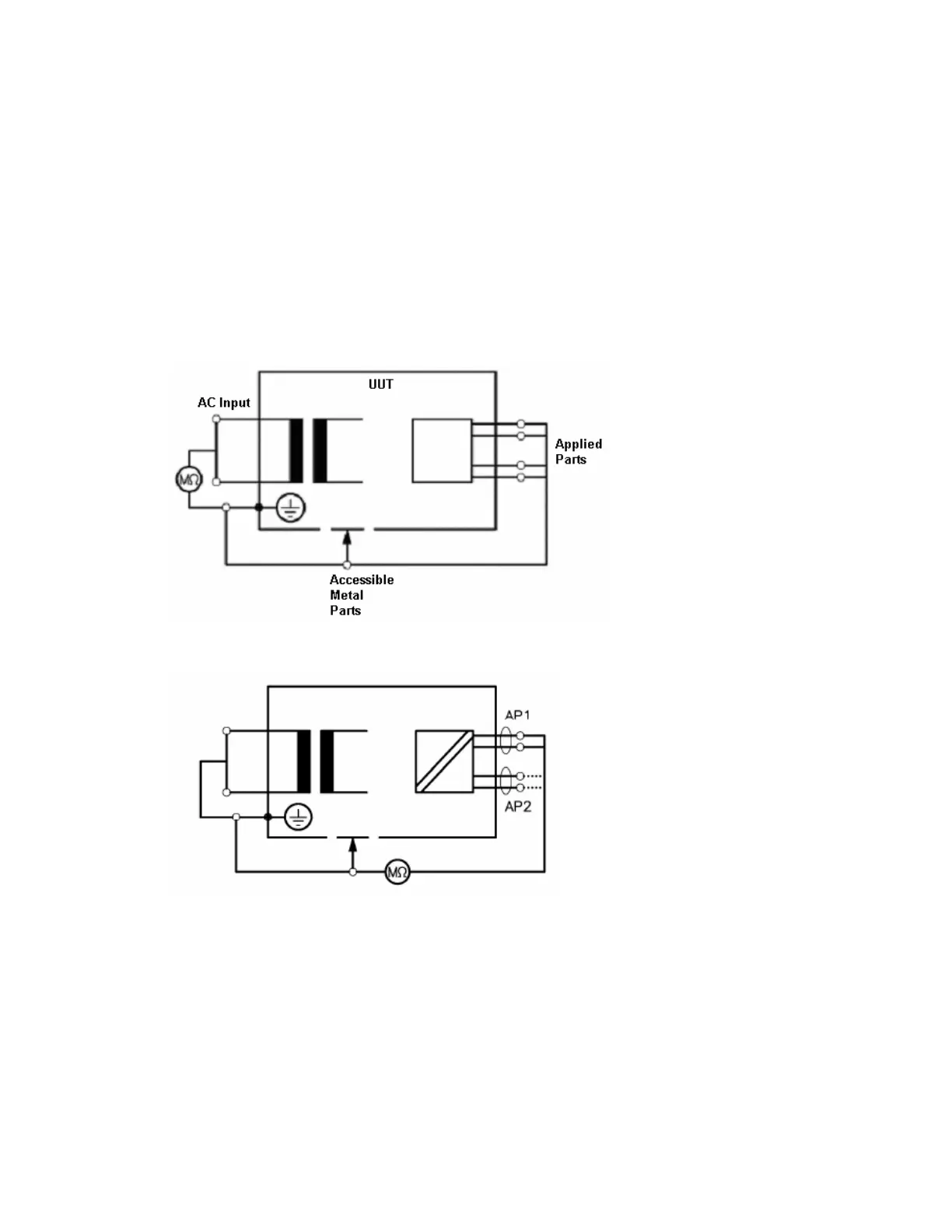
Insulation Resistance
Perform the following tests, with the applicable resistance range settings and record the results in the applicable test
form(s).
1. Disconnect from the SUPPLY MAINS
2. Remove battery
3. Remove I/O (RS-232) cable
4. UUT power switch in the “ON” position.
The resistance values shall not be less than:
• 2 MΩ between MAINS PART and all other parts separated by basic insulation, including TYPE B APPLIED
PARTS
• 7 MΩ between MAINS PART and all other parts separated by double insulation, including TYPE B APPLIED
PARTS
• 70 MΩ between MAINS PART to any F-TYPE APPLIED PART
Accessible Metal Parts Insulation Resistance
• The resistance value shall not be less than: 7 MΩ
MAINS PART to “F-TYPE APPLIED PARTS” insulation resistance
• The resistance value shall not be less than: 70 MΩ