Section 5: Performance Verification and Safety Testing
2025653-048 Revision B Responder
™
2000 Page 80
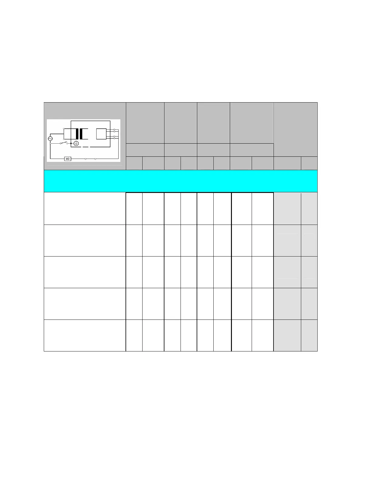
Patient Leakage Current to Ground
Perform the following tests, with the applicable switch settings on the “Safety Tester” and record the results in the
applicable test form(s).
• UUT power switch in the “ON” position.
• TP1 connected to “Applied Parts” (see tables below for individual test points).
Note: The following applied parts have a separate isolated input and have to be tested separately.
• Leads
• Paddles
• SpO
2
S1: DPDT
Polarity
a) Normal
b) Reverse
S2: SPDT
Neutral
a) Closed
b) Open
S3: SPDT
Ground
a) Closed
b) Open
S4: SPDT
Test point
a) Internal
b) TP1
Position Position Position Position
Maximum
Limits
(uA)
Test Description
a b a b a b a b EN/IEC UL
Patient leakage current measurements: LEADS
TP1 connected to “LEADS” (all LEADS connected together), Type CF defibrillation proof limits
Polarity: Normal
Neutral: Normal (Closed)
Ground: Normal (Closed)
X X X X
10 10
Polarity: Normal
Neutral: Open
Ground: Normal (Closed)
X X X X
50 50
Polarity: Normal
Neutral: Normal (Closed)
Ground: Open
X X X X
50 50
Polarity: Reverse
Neutral: Normal (Closed)
Ground: Open
X X X X
50 50
Polarity: Reverse
Neutral: Open
Ground: Normal (Closed)
X X X X
50 50