Section 5: Performance Verification and Safety Testing
2025653-048 Revision B Responder
™
2000 Page 83
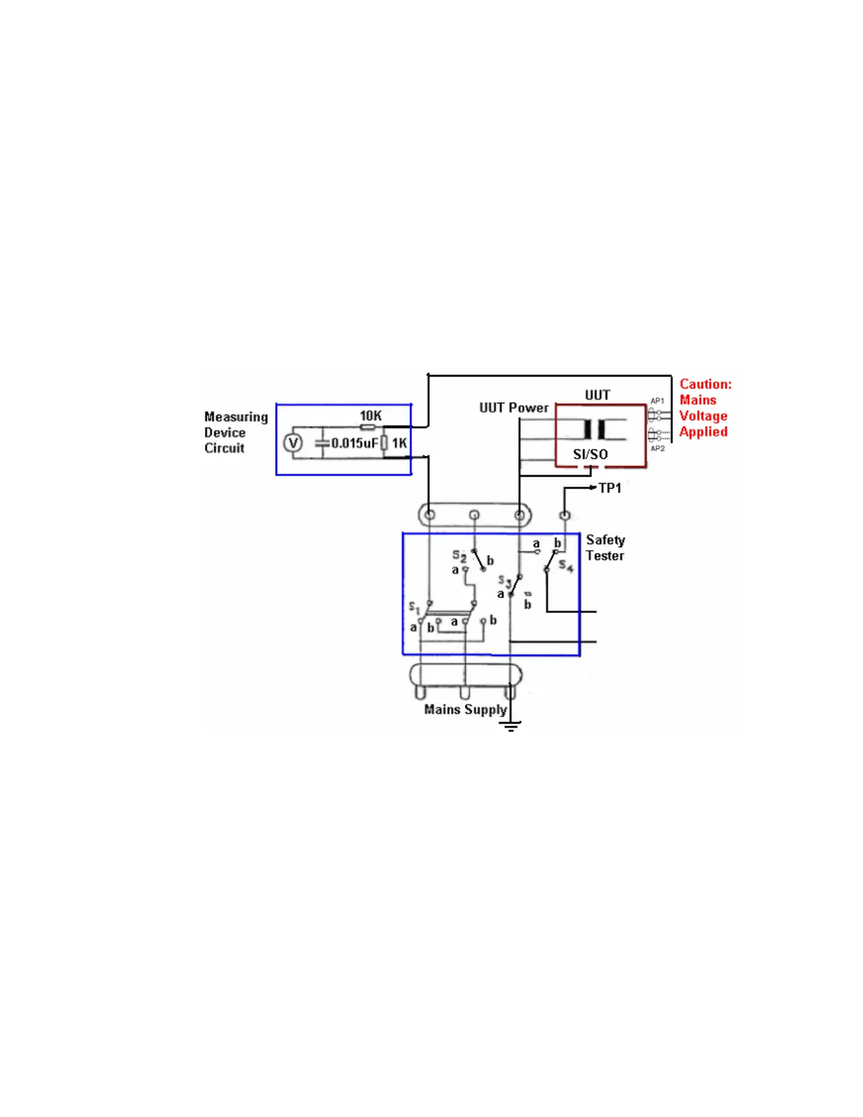
Patient Leakage Current, Mains on Applied Part (All SIP/SOPs Grounded)
Perform the following tests, with the applicable switch settings on the “Safety Tester” and record the results in the
applicable test form(s).
1. Disconnect the “Safety Tester” from the “Mains Supply”
2. Ensure the battery is removed
3. Configure the test set up as shown (or equivalent)
• UUT hot/neutral/ground connected to ground
• All accessible metal parts (i.e. DB9 shell and exposed metal of printer) connected to ground
4. UUT power switch in the “ON” position.
Caution:
Use care when connecting the “Safety Tester” to the “Mains Supply”, mains voltage will appear on the applied parts.
Caution:
Use care when selecting switch settings (S2 should be open, S3 = safety ground)
Note: The following applied parts have a separate isolated input and have to be tested separately.
• Leads
• Paddles
• SpO
2