SECTION 4: Repair
2025653-048 Revision B Responder
™
2000 Page 43
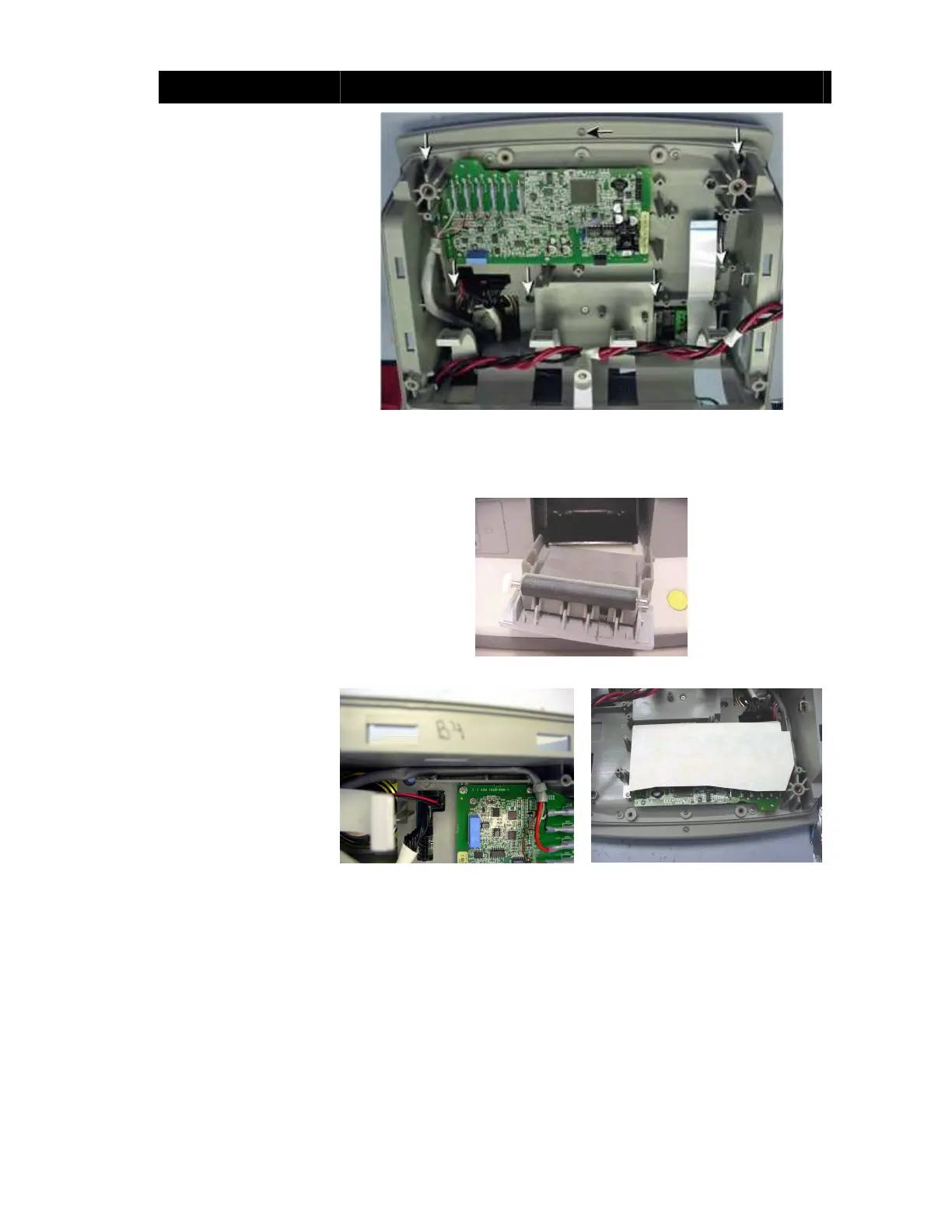
Assembly Step Details
If necessary, remove
protective paper and plastic
from inside the Front
Bezel.
Caution: Equipment
Damage. Do not touch the
inside of the Front Bezel.
Clean the LCD and inside
of the Front Bezel with a
brush or compressed air.
Ensure the plastic is clean
and not scratched.
Install the Front Bezel with
six Torx security screws
(white arrows) and one
Phillips screw (black arrow).
Note: Install the Front
Bezel before assembling
the circuit boards on the
main compartment of the
unit; otherwise you might
not be able to access the
Front Bezel screws.
Figure 45: Front Bezel Installed
Install the Printer Door into
the Front Body (insert the
left side and then snap the
right side into place.
Note the roller orientation.
The left side of the door is
inserted first.
Open and close the door
several times to ensure
proper installation.
Figure 46: Printer Door Installation
Route the ECG cable and
connect the remaining gray
ECG cable connector to the
clip in the ECG Shield.
Install the ECG Shield in
the Front Body with three
Phillips screws.
Figure 47: ECG Cable
(Properly Routed)
Figure 48: ECG Shield Installed