THR.CRV
Throttle Control Stick Characteristic Settings
This submenu icon is not available for motor-less gliders.
Use this submenu to change the control character-
istic of the throttle and control stick independent of
whether the control function acts directly on a servo
connected to control channel 1, or via a number of
mixers on multiple servos. Also use this submenu to
adjust the idle LOW or “motor off” throttle position.
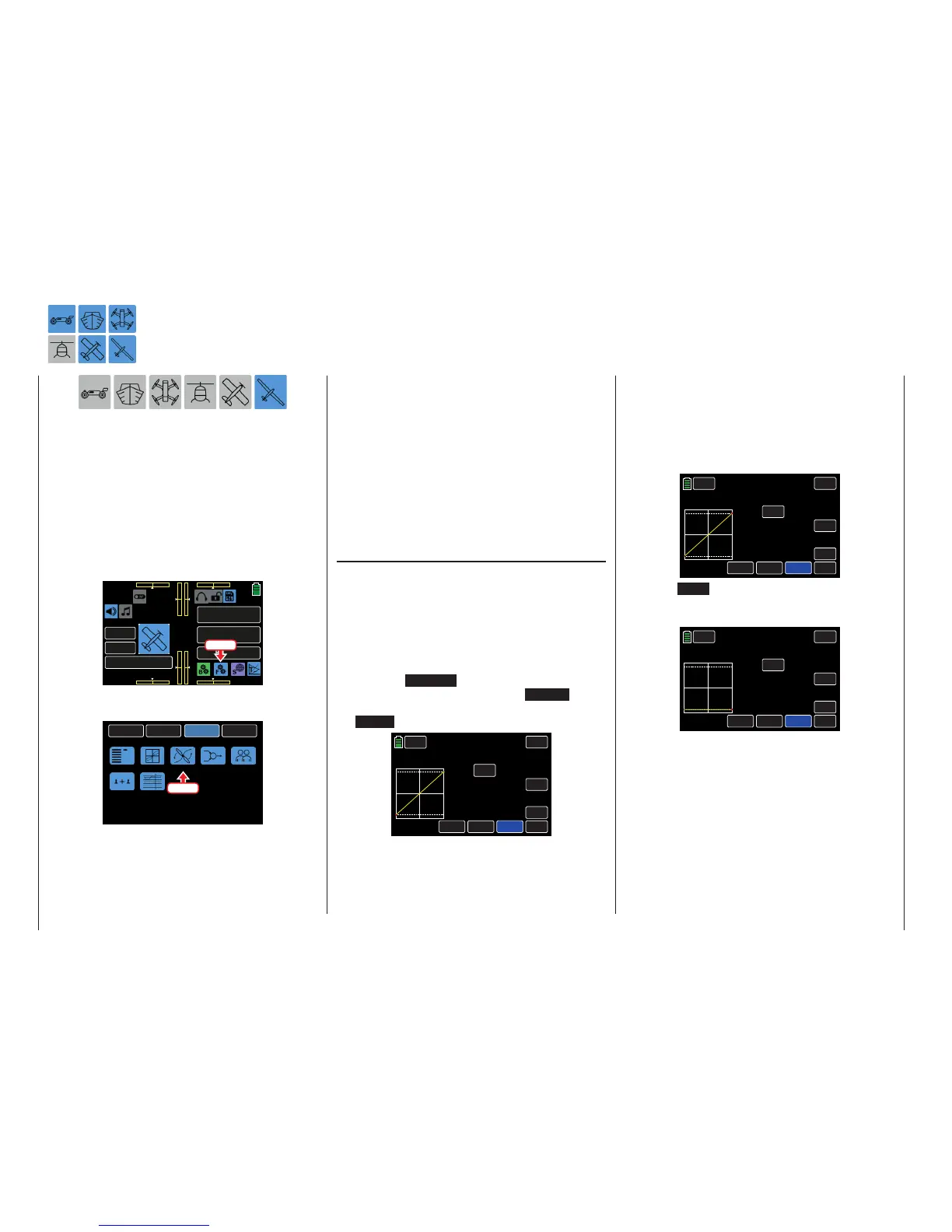
To change these settings, from the main display press
the FUNCTION menu gear icon (blue “F”) to bring up
the FUNCTION submenu screen:
000
000
000
000
mz
000%
000%
BATT TIME 00: 01: 23
MODELLNAME 1
M - 1
PHASE 1
000:00.0
000:00.0
4.2V
0:01:23
Press
From the FUNCTION submenu display, press the
THR.CRV icon:
BACK
SYSTEM
BASE
FUNCTION
Phase
D/R,EXP
THR.CRV
Prog.MIX
Trainer
Sequence
Logical sw
Press
Phase Dependent Settings
This submenu allows for different phase-specific val-
ues to be programmed. Phase names are displayed
in green in the upper left side of the screen next to
the BACK button. Standard default naming for the
phases are usually displayed as NORMAL/PHASE
1. (Additional phases will be named numerically, e.g.
Phase 2, Phase 3, etc.) To define multiple phases,
refer to the FUNCTION submenu Phase section (page
120). Each new phase will need to be assigned to a
different switch. To change the phases, activate the
corresponding switch(es).
Changing the Control Direction
In the mz-24 PRO transmitter, all fixed-wing rear
throttle positions default to Motor OFF when using
electric drives. The throttle control stick control di-
rection can be inverted through the throttle curve from
"accelerate from back to front" to "accelerate from
front to back".
To make adjustments to this function, turn on the
control stick position graphic/numerical display by
pressing the ST OFF button at the bottom left of
the display to change the value to ST ON . Acti-
vate the Y-coordinate adjustment option by pressing
the Y-axis button:
BACK
PHASE 1
IN
OUT
POINT
OFF
INC
ENT
DEC
Y-axis
X-axis
ST ON
CURVE
–100%
–100%
000%
L
SERVO
TRH.CRV
Use the throttle to move the vertical green line be-
tween the two endpoints L and H in the graphic.
The control stick position is also displayed numerical-
ly in the IN line (-100 % to +100 %).
Move the throttle to one of the two end positions. In
the example below, the throttle is moved to the front
position and the green line moves the right, disap-
pearing under the white frame, and the color of the
top point changes from green to red:
BACK
PHASE 1
IN
OUT
POINT
OFF
INC
ENT
DEC
Y-axis
X-axis
ST ON
CURVE
+100%
+100%
+100%
L
SERVO
THR.CRV
Press the DEC button or the down arrow key ( q )
to move the red point down to a value of 000% in the
POINT line:
PHASE 1 THR.CRV
BACK
IN
OUT
POINT
OFF
INC
ENT
DEC
Y-axis
X-axis
ST ON
CURVE
+100%
–100%
000%
H
SERVO
Move the throttle to the opposite end position. In the
example below, the throttle is moved to the rear posi-
tion and the green line moves to the left, disappearing
under the white frame, and the point at the end of the
yellow horizontal line change from green to red:
128 Function menu | general - Curve CH 1

 Loading...


