Setting the servo directions is necessary for to main-
tain the model's control system. Improperly set con-
trol movements will cause the model to crash.
To set the servos, from the main display press the
BASE menu gear icon (green "B") to bring up the
BASE submenu screen:
000
000
000
000
mz
000%
000%
BATT TIME 00: 01: 23
MODELLNAME 1
M - 1
PHASE 1
000:00.0
000:00.0
4.2V
0:01:23
Touch
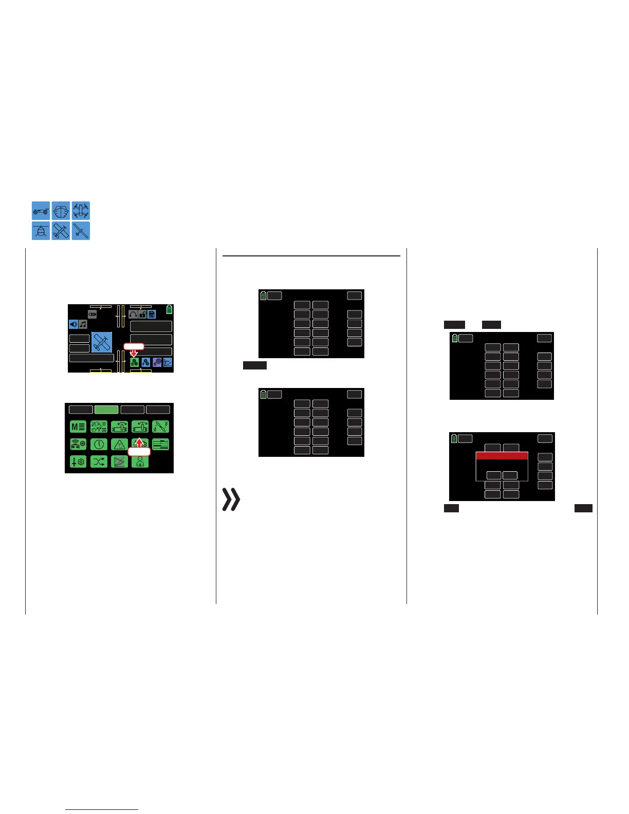
From the BASE submenu display, press the REV/SUB
icon:
BACK
SYSTEM
BASE
FUNCTION
Model Sel
E.P.A
Model Type
REV/SUB
THR.CUT
Timer
TX ctl
Fail Safe
Trim Step
Servo
Out.Swap
CTL Set
Announce
Telemetry
Press
REV/SUB
Setting Servo Direction and Neutral Position
Servo Direction and Neutral Position
Servo direction adjustments are done in the left REV
column, the related center position adjustments are
done in the right SUB.TR column:
BACK
SERVO
CH 1.
CH 2.
CH 3.
CH 4.
CH 5.
CH 6.
INC
RES
DEC
000%
000%
000%
000%
000%
000%
NOR
NOR
NOR
NOR
NOR
NOR
REV
SUB.TR
NEXT
Press NEXT button on the right side of the display to
scroll through the channel screens:
BACK
SERVO
CH 7.
CH 8.
CH 9.
CH 10.
CH 11.
CH 12.
INC
RES
DEC
000%
000%
000%
000%
000%
000%
NOR
NOR
NOR
NOR
NOR
NOR
REV
SUB.TR
NEXT
Notices
• Always begin by setting the direction in which
the servos have to move before setting the
other parameters!
• The servo numbering refers to the servos
connected to the corresponding receiver out-
puts, providing that the transmitter and re-
ceiver outputs have not been switched. This
allows for a change in the control mode that
will not change the numbering of the servos.
1. Setting Servo Direction
With this option, the servo rotation direction is
adapted to the specifics in the particular model so
that, when the control linkages and articulations
are installed, the servo's rotational direction does
not have to be considered.
The travel direction is reversed by pressing
to change the corresponding value fields la-
beled NOR and REV:
BACK
SERVO
CH 1.
CH 2.
CH 3.
CH 4.
CH 5.
CH 6.
INC
RES
DEC
000%
000%
000%
000%
000%
000%
NOR
REV
NOR
NOR
REV
NOR
REV
SUB.TR
NEXT
Whenever the travel direction of CH6 (in a helicop-
ter) or CH1 (in the other model types) is changed,
an Active Warning will be displayed:
BACK
SERVO
CH 1.
CH 2.
CH 3.
CH 4.
CH 5.
CH 6.
INC
RES
DEC
000%
000%
000%
000%
000%
000%
NOR
UMK
NOR
NOR
REV
NOR
REV
SUB.TR
NEXT
YES
NO
SURE?
Warning
Press NO to terminate the procedure. Press YES
to change the servo travel direction connected to
CH1 or CH6.
64 Base menu - Servo reverse/Servo center

 Loading...


