Sequencer
Logical Switch Setup
A sequence allows up to three servos to perform up to
nine steps during a 30-second period. For example,
sequencing can allow the cover doors to open while
folding landing gear descends the fuselage, then close
again when the landing gear leg has extended. Alter-
natively, sequencing can allow the canopy to open,
the pilot turn his head and wave his hand. All of these
actions must first be divided into a logical sequence
of single movements.
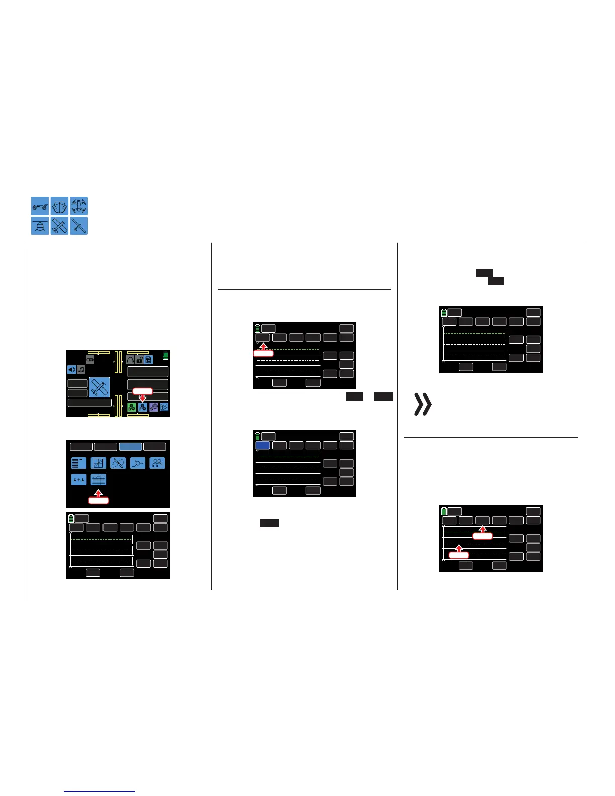
To set a sequence, from the main display press the
FUNCTION menu gear icon (blue “F”) to bring up the
FUNCTION submenu screen:
000
000
000
000
mz
000%
000%
BATT TIME 00: 01: 23
MODELLNAME 1
M - 1
PHASE 1
000:00.0
000:00.0
4.2V
0:01:23
Press
From the FUNCTION submenu display, press the Se-
quence icon:
BACK
SYSTEM
BASE
FUNCTION
Phase
D/R,EXP
THR.CRV
Prog.MIX
Trainer
Sequence
Logical sw
Press
INH
00.0s
INC
RES
DEC
000
0
NULL
TIME
POS
INH
BACK
SERVO
Sequence
CH10 INH
CH11
CH9
STEP
CTL
Through the Sequence display, one common switch
can be assigned to activate up to three servos per-
forming up to 9 precisely determined steps within 30
seconds.
Selection and Control Channel Activation
• Channel Selection
The three pre-set channels CH9, CH10 and CH11
can be changed by pressing the value field:
INH
00.0s
INC
RES
DEC
000
0
NULL
TIME
POS
INH
BACK
SERVO
Sequence
CH10 INH
CH11
CH9
STEP
CTL
Press
The field highlights blue. Press the INC or DEC
button or the arrow keys ( pq ) to scroll through
the available channels (5 - 12). In the example be-
low, the default CH9 field is changed to CH6:
INH
00.0s
INC
RES
DEC
000
0
NULL
TIME
POS
INH
BACK
SERVO
Sequencer
CH10 INH
CH11
CH6
STEP
CTL
Use the same procedure with the other channel
value fields.
Press the RES button to reset the changed value
back to the default.
• Activation / Deactivation
The control channels specifically required for the
channel sequencing are activated and deactivat-
ed by pressing the INH buttons next to the chan-
nel fields to change to ON and vice versa. In the
example below, all channels have been changed
to ON:
ON
00.0s
INC
RES
DEC
000
0
NULL
TIME
POS
ON
BACK
SERVO
Sequence
CH7 ON
CH8
CH6
STEP
CTL
Notice
All control functions activated in the FUNC-
TION submenu Sequence are unavailable for
other uses.
Sequencing
• STEP 0: Setting the Output Position
The output position can be activated in one of two
ways. Press any channel field to highlight the but-
ton blue. The corresponding output position line
highlights green. Or, press any output position
line to highlight green. The corresponding channel
field button highlights blue:
ON
00.0s
INC
RES
DEC
000
0
NULL
TIME
POS
ON
BACK
SERVO
Sequence
CH7 ON
CH8
CH6
STEP
CTL
Press
Press
150 Function menu | general - Sequencer

 Loading...


