If the center position of the self-centering control
stick (controls 1 - 4) does not precisely correspond to
000%control travel, it can be checked and corrected.
Maintaining 000% control travel is important for prop-
er flight and function of the servo and controls.
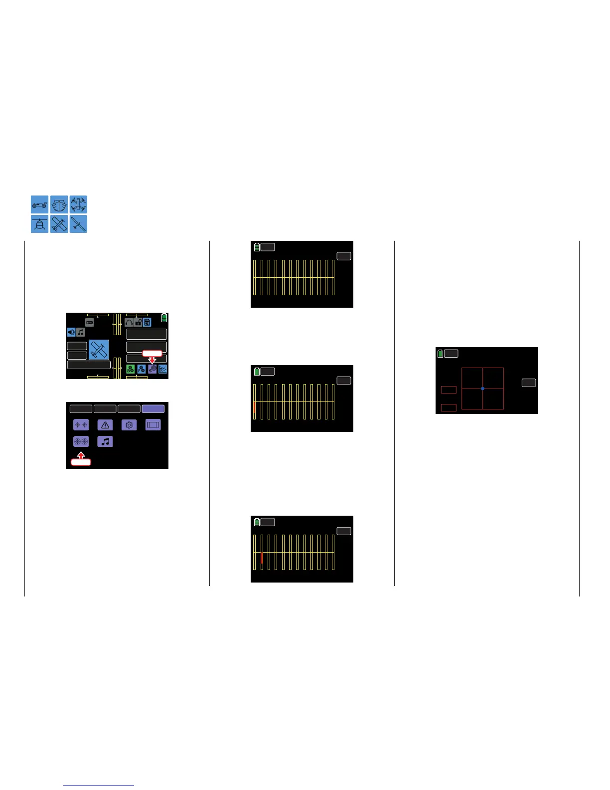
To adjust these settings, from the main display press
the SYSTEM menu gear icon (purple “S”) to bring up
the SYSTEM submenu screen:
000
000
000
000
mz
000%
000%
BATT TIME 00: 01: 23
MODELLNAME 1
M - 1
PHASE 1
000:00.0
000:00.0
4.2V
0:01:23
Touch
From the SYSTEM submenu, press the Stick Cali
icon:
BACK
SYSTEM
BASE
FUNCTION
ST mode
Etc. Set
Warning
Display
MP3
Stick Cali
Press
To calibrate the self-centering control stick, select a
free model memory slot in the BASE submenu Model
Sel to make a dummy model for calibration purposes
only. Model type is irrelevant; it is only important that
no trimming or programming has yet been performed.
Open the BASE submenu Servo by simultaneously
pressing the arrow keys ( pq ) on the left of the dis-
play.
If all four of the transmitter's control stick functions
are self-centering, this display should ideally look like
the example shown here:
Stick Cali
Control Stick Center Position Calibration
BACK
TEST
1 2 3 4 5 6 7 8 9 10
11
12
000%
000%
000%
000%
000%
000%
000%
000%
000%
000%
000%
000%
Servo
PHASE 1
If all four of the transmitter’s control stick functions
are NOT self-centering, the graph bars show current
setting percentages for control stick control functions
which are not self-centering (traditionally CH1). For
example, if the CH1 control stick is in its Idle LOW
position, the display would appear follows:
BACK
TEST
1 2 3 4 5 6 7 8 9 10
11
12
000%
000%
000%
000%
000%
000%
000%
000%
000%
000%
000%
Servo
PHASE 1
–100%
One at a time, put each control stick into their four
possible limit positions without exerting force at the
limit position. In each of these eight possible limit
positions, the (side dependent) indication for exactly
-100% or +100% should be displayed. For example,
if Control 2 is at its right limit and the other three other
control stick functions are in their respective middle
positions, then the servo display should appear as
follows:
BACK
TEST
1 2 3 4 5 6 7 8 9 10
11
12
-100%
000%
000%
000%
000%
000%
000%
000%
000%
000%
000%
Servo
PHASE 1
000%
Regardless of the number of self-centering control
stick functions available on the transmitter, if these
checks produce four 000% results and eight 100%
results, then the transmitter's control sticks are op-
timally calibrated. Terminate this process and then,
if necessary, delete the dummy model memory just
created.
If the control sticks are not optimally calibrated, open
the SYSTEM submenu Stick Cali. This display allows
users to cycle through the four stick lever positions
for calibration, starting with the neutral position of the
right control stick system:
Stick Cali
BACK
<< RIGHT >>
VERTI.
HORIZ.
–078%
+002%
SET
The blue dot shown in the above graphic indicates the
stick position to be adjusted.
The horizontal and vertical percentages displayed in
the VERTI and HORIZ column value fields indicate the
current stick position.
Although the right-hand stick is located exactly in the
middle of its path (due to its horizontal self-centering),
the example above shows an adjustment of +002%.
220 System menu - Joystick calibration

 Loading...


