PIT.CRV
Phase-Specific Pitch Control Curve Setup
Use this function to set adjustments to the pitch of he-
licopter blades at certain stick positions. For exam-
ple, when the control stick is all the way forward with
the intent for the helicopter to quickly fly straight up,
the curve should be programmed for maximum pitch
on the blades. Conversely, when the helicopter is shut
down for a stop, the curve should be programmed for
little or no pitch on the blades.
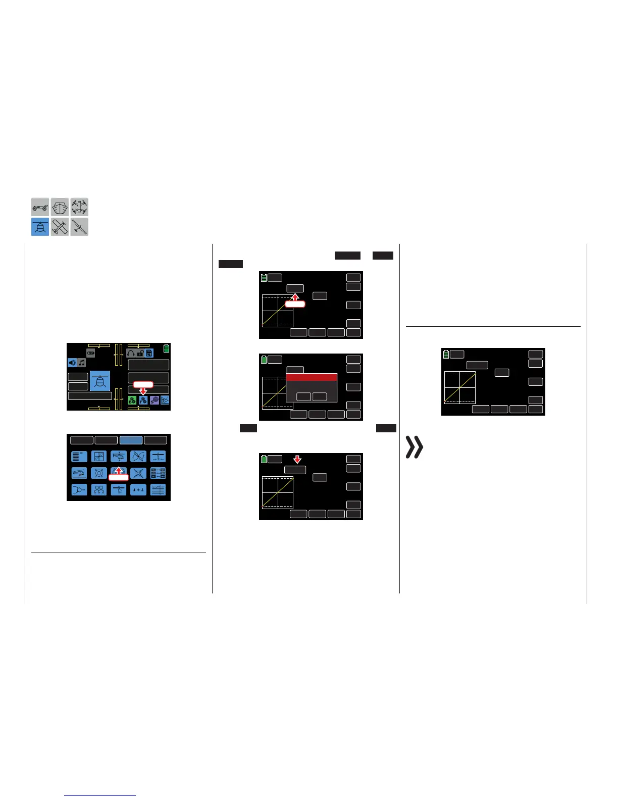
To adjust these settings, from the main display press
the FUNCTION menu gear icon (blue “F”) to bring up
the FUNCTION submenu screen:
000
000
000
000
mz
000%
000%
BATT TIME 00: 01: 23
Starlet
M - 3
PHASE 1
000:00.0
000:00.0
4.2V
0:01:23
Press
From the FUNCTION submenu display, press the PIT.
CRV icon:
BACK
SYSTEM
BASE
FUNCTION
Phase
S.Limit
D/R,EXP
THR.CRV
Gyr/Gover
Swash
THR.HOLD
PIT.CRV
S.MIX
THR.MIX
Trainer
Prog.MIX
Logical sw
PIT>>TAIL
Sequence
Press
A curve mixer is available in every flight phase for
pitch curve settings. However, linear mixers cannot
be programmed for actions analog to the control stick
travels.
Pitch min Line
In the mz-24 Pro, the helicopter program defaults the
"rear" throttle to the Pitch min position.
This option allows users to easily reverse the pitch
control stick control direction from the standard pre-
set position Pitch min BACK to Pitch min FOR-
WARD, and vice versa. Press the BACK or FOR-
WARD button in the Pitch min line:
PHASE 1
SERVO
PIT.CRV
BACK
IN
OUT
POINT
INC
ENT
DEC
Y-axis
TRIM
X-axis
ST OFF
CURVE
–100%
–100%
–100%
L
Pitch min
BACK
OFF
Press
An active warning message appears:
PHASE 1
SERVO
PIT.CRV
BACK
EIN
AUS
POINT
INC
ENT
DEC
Y-axis
TRIM
X-axis
ST OFF
KURVE
–100%
–100%
–100%
L
Pitch min
BACK
AUS
YES
NO
SURE?
Warning
Press NO to terminate the procedure. Press YES
to confirm, and the pitch control stick travel direction
changes:
PHASE 1
SERVO
PIT.CRV
BACK
IN
OUT
POINT
INC
ENT
DEC
Y-axis
TRIM
X-axis
ST OFF
Curve
–100%
–100%
–100%
L
Pitch min
FORWARD
OFF
Inverted control signals act on the following: mixed
and coupling functions and the throttle position active
Power OFF time.
Phase-dependent settings of the pitch curves
This submenu allows for different phase-specific val-
ues to be programmed. Phase names are displayed
in green in the upper left side of the screen next to
the BACK button. Standard default naming for the
phases are usually displayed as NORMAL/PHASE
1. (Additional phases will be named numerically, e.g.
Phase 2, Phase 3, etc.) To define multiple phases,
refer to the FUNCTION submenu Phase section (page
120). Each new phase will need to be assigned to a
different switch. To change the phases, activate the
corresponding switch(es).
Pitch Curve Setting
Use this display to adapt the pitch curve as needed,
and assign to different phases if necessary:
PHASE 1
SERVO
PIT.CRV
BACK
IN
OUT
POINT
INC
ENT
DEC
Y-axis
TRIM
X-axis
ST OFF
Curve
–100%
–100%
–100%
L
Pitch min
FORWARD
OFF
Notice
The example graphs represent the curve charac-
teristics directly, independent from the actual di-
rection selected on the pitch control stick.
The pitch control curve can be specified by up to 7
points (termed “support points”) along the entire con-
trol stick travel.
During initial setup, fewer support points are required
to set a pitch curve. However, it is recommended to
start with at least three support points.
These three endpoints describe the linear character-
istic of a pitch control curve: the two endpoints Pitch
low (L = -100% control travel) and Pitch high (H =
+100% control travel) and the control (placed in the
center).
154 Function menu | Helicopter model - Pitch curve

 Loading...


