Gyro/Governor
Gyro and Governor Settings
The gyro detects any yaw movement (left or right
swinging) of the model and automatically sends a
command to the tail rotor servo to correct and stop/
limit the movement. The gyro will not allow the heli-
copter to turn until the tail rotor command is correct-
ed.
The governor maintains a constant speed in the sys-
tem being monitored by independently regulating the
provided output and only requiring a speed setting
(not a classic throttle curve).
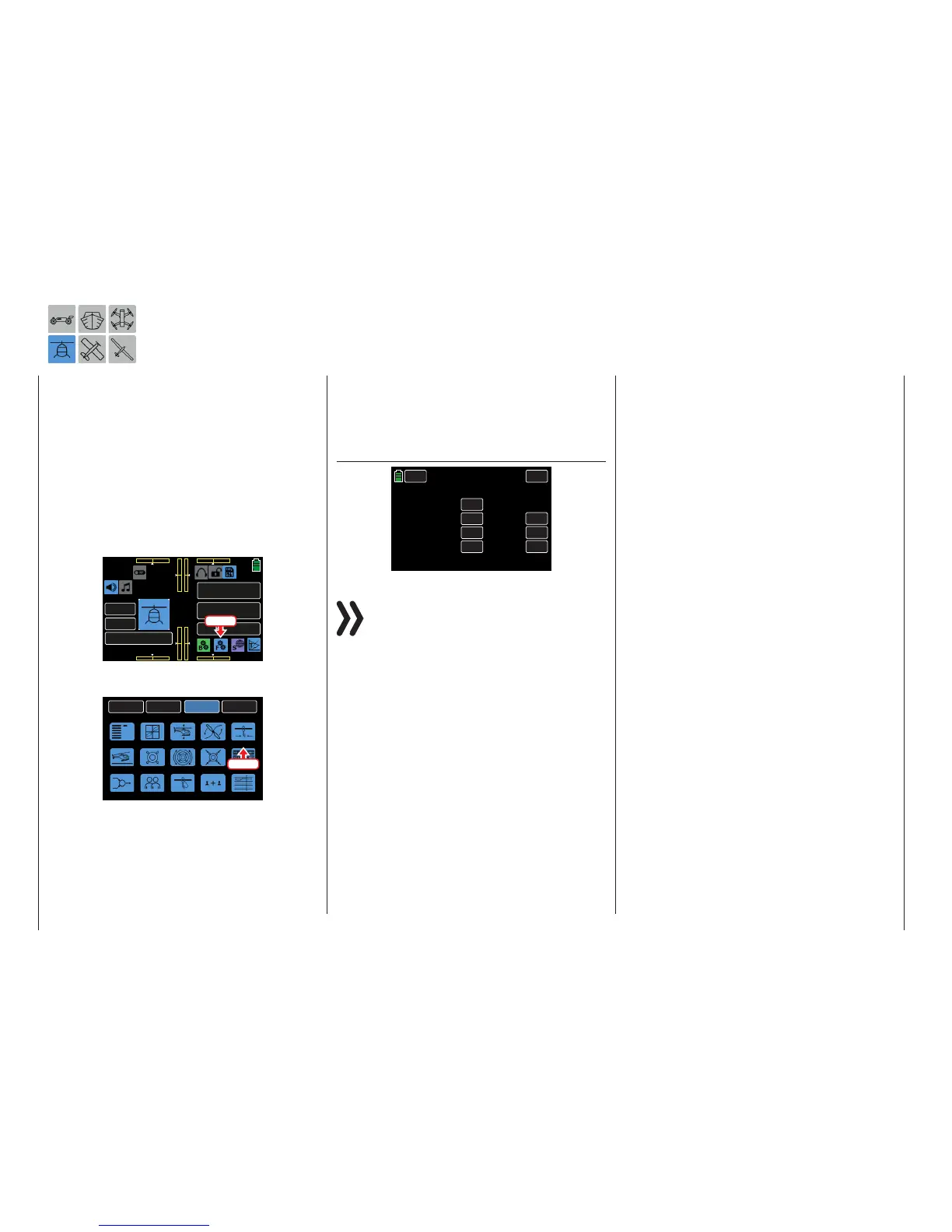
To adjust these settings, from the main display press
the FUNCTION menu gear icon (blue “F”) to bring up
the FUNCTION submenu screen:
000
000
000
000
mz
000%
000%
BATT TIME 00: 01: 23
Starlet
M - 3
PHASE 1
000:00.0
000:00.0
4.2V
0:01:23
Press
From the FUNCTION submenu display, press the Gyr/
Gover icon:
BACK
SYSTEM
BASE
FUNCTION
Phase
S.Limit
D/R,EXP
THR.CRV
Gyr/Gover
Swash
THR.HOLD
PIT.CRV
S.MIX
THR.MIX
Trainer
Prog.MIX
Logical sw
PIT>>TAIL
Sequence
Press
Gyro/Governor Phase-Dependent Settings
This submenu allows for different phase-specific val-
ues to be programmed. Phase names are displayed
in green in the upper left side of the screen next to
the BACK button. Standard default naming for the
phases are usually displayed as NORMAL/PHASE 1.
(Additional phases will be named numerically, e.g.
Phase 2, Phase 3, etc.) To define multiple phases,
refer to the FUNCTION submenu Phase section (page
120). Each new phase will need to be assigned to a
different switch. To change the phases, activate the
corresponding switch(es).
Gyro Suppression Line
BACK
Gyro Gain
000%
Gyro Suppression
Governor RATE
Governor ACT
000%
INH
050%
RES
DEC
INC
PHASE 1
SERVO
Gyr/Gover
Notice
Many current standard gyro systems do not re-
quire this option to be utilized; consult the gyro
setting instructions in the model’s manual. Using
this option if it is not required may make it impossible to
fly the helicopter.
If the model can use a gyro system in which the gy-
ro’s effect is set by the transmitter using an additional
channel (CH7 in the Graupner remote-control system),
this option can influence the effect of the gyro sensor
(gyroscope) as the tail rotor control stick is moved.
The gyro suppression reduces the gyro's effect in a
linear manner in proportion to the deflection of the tail
rotor control stick corresponding to the set value. If
the gyro has not been suppressed (at a value of 0%),
the gyro's effect remains independent of the control
stick deflection.
The gyro's effect can be varied (depending on the
phase) between a minimum and maximum using a
control assigned in the OFFSET column of the BASE
submenu CTL Set. For example, pilots may assign
one of the side proportionaldials SL1 or SL2. The
maximum gyro gain occurs at the full deflection of the
control and is zero at the opposite limit. In the pro-
gram, pilots are free to restrict the effective range to
both sides by setting the control travel.
Depending on the position of the control, the gyro
gain is as follows in response to the full deflection of
the tail rotor control control stick:
Momentary control position
minus
the value of the gyro suppression.
If the gyro is in the neutral position and gyro suppres-
sion is set, the gyro's effect is reduced from 100%
to zero with increasing tail rotor excursion. For values
between 100% and a maximum of 199%, full gyro
suppression is achievable before full tail rotor excur-
sion depending on the control position (see figure s
on page 166).
With the Graupner/JR-Gyro NEJ-120 BB, No. 3277,
both the bottom and top values are set: control 1 sets
the minimum gyro gain in the bottom position of the
servo, control 2 sets the maximum effect in the top
end position of the servo. The switch between these
two values occurs approximately in the center of the
servo travel.
The gyro systems PIEZO 900, PIEZO 2000 and PIEZO
3000 contrastingly feature proportional, infinitely vari-
able adjustment of gyro gain (see the following exam-
ple graphs).
For example, the option to configure static or
phase-specific gyro gain gives you the opportunity to
exploit maximum stabilization for normal, slow flying,
but reduces gyro gain for fast circuits and aerobatics.
166 Function menu | Helicopter model - Gyro/Gover

 Loading...


