Control and Switch Assignment
Basic Procedure
Many options and settings can be actuated to a con-
trol function with a freely selectable control (ST1 - 4,
DV1 - 4, DT1 and DT2, SL1 and SL2), switch (S1 - 8),
or logical switch (see Assigning a Logical Switch or
Control, page 27). In all cases, multiple assignments
are possible. Refer to the Definition of Terms section
(page 24) to distinguish between a control and switch.
Notice
Note that incorrect responses may arise from
functional overlaps, e.g. using the same switch to
toggle between Phase changes and a control for
Phase trimming. The functions are incompatible and the
switch assignment should be changed.
The same method is used to assign the controls,
switches, control switches and logical switches in
all relevant menus. The basic procedure will be ex-
plained below; refer to the specific submenu sections
for details on individual functions.
Control and Switch Assignment
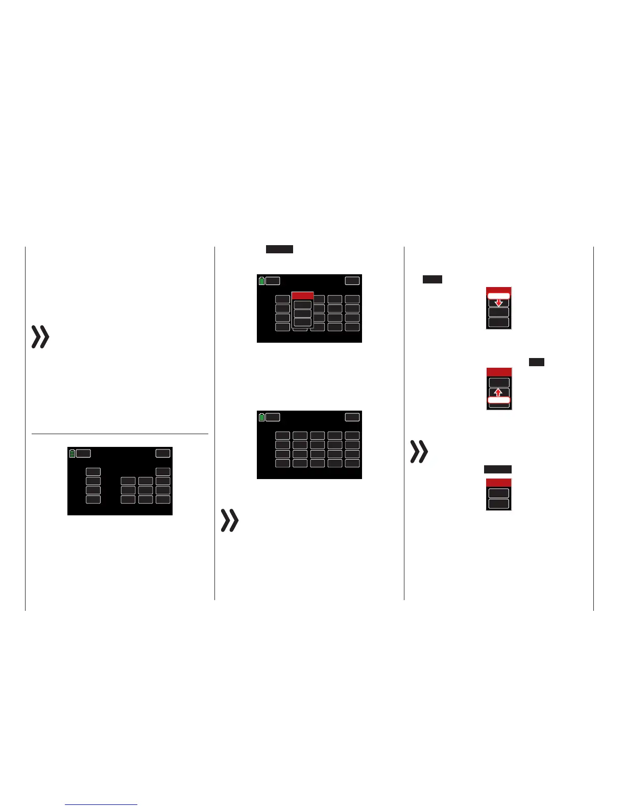
Open the BASE submenu CTL Set:
CH 1.
CH 2.
CH 3.
CH 4.
ST 1
ST 2
ST 3
ST 4
INC
RES
DEC
+100%
+100%
+100%
+100%
+100%
+100%
CTL
– Travel+
NEXT
BACK
SERVO
CTL Set
PHASE 1
OFFSET
Use this display to assign transmitter inputs 1 - 12
to operate servos, any control stick (ST1 - ST4), any
switch (S1 - S8), or any control (DV, SL or DT).
Pressing the NONE button in any channel line will
bring up an active window. In the example below, the
CH 5 line needs a control assigned to SL1:
CH 5.
CH 6.
CH 7.
CH 8.
NONE
NONE
NONE
NONE
0%
0%
0%
0%
+100%
+100%
+100%
+100%
+100%
+100%
+100%
+100%
CTL
– Travel +
BACK
SERVO
CTL Set
PHASE 1
OFFSET
INC
RES
DEC
NEXT
Select
CLR
NO
LOGIC
To assign a switch, simply move the desired control
(stick 1 - 4, DV1 - DV4, SL1 - SL2, or DT1 - DT2) or
the desired switch (S1 - S8). Once the switch, con-
trol or control stick is assigned the active window will
disappear. In the example below, the right proportion-
al rotary control SL1 was flipped and the assignation
shows in the CTL column of the CH 5. line:
CH 5.
CH 6.
CH 7.
CH 8.
SL 1
NONE
NONE
NONE
0%
0%
0%
0%
+100%
+100%
+100%
+100%
+100%
+100%
+100%
+100%
CTL
– Travel +
BACK
SERVO
CTL Set
PHASE 1
OFFSET
INC
RES
DEC
NEXT
Note
The controls are only recognized along a specific
path. Move the control to the left or right, forward
or backward until the assignation appears in the
display. If the length of travel is insufficient, move the
control in the opposite direction.
Deleting Controls or Switches
To delete, press the value field of the switch or control
to be removed. The active window will appear. Press
the CLR button:
Select
CLR
NO
LOGIC
Press
The field returns to its default value (NONE).
Canceling Control or Switch Assignment
To cancel an assignment, press the NO button:
Select
CLR
NO
LOGIC
Press
The active menu will disappear.
Notice
For certain menu options, only physical controls
or switches can be assigned. When the logical
switch option is unavailable, the active windows
will appear without the LOGIC button:
Select
CLR
NO
This is not an error.
26 Control and switch assignment

 Loading...


