BATT TIME 00: 01: 23
MODELLNAME 1
M - 1
PHASE 1
000:00.0
000:00.0
4.2V
0:01:23
Press
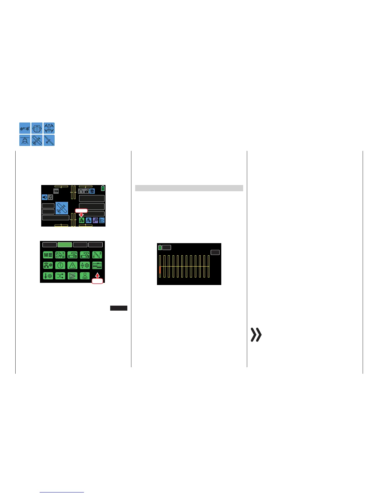
From the BASE submenu display, press the Servo
icon:
BACK
SYSTEM
BASE
FUNCTION
Model Sel
E.P.A
Model Type
REV/SUB
THR.CUT
Timer
TX ctl
Fail Safe
Trim Step
Servo
Out.Swap
CTL Set
Announce
Telemetry
Press
The Servo display can be accessed at any time by
simultaneously pressing the arrow keys ( pq ) to the
left of the display screen or by pressing the SERVO
button in the upper right hand corner of certain menu
screens. Pressing the ESC key underneath the arrow
keys brings up the previous screen.
Phase Depending Displays
The Servo submenu allows for different phase-spe-
cific values to be programmed. Phase names are dis-
played in green in the upper left side of the screen
next to the BACK button. Standard defaults naming
for the phases is usually displayed as NORMAL, or
PHASE 1. (Additional phases will be named numer-
ically, e.g. Phase 2, Phase 3, etc.) To define multi-
ple phases, refer to the FUNCTION submenu Phase
section (page 120). Each new phase will need to be
assigned to a different switch. To change the phases,
activate the corresponding switch(es).
Servo monitor
Current servo settings are displayed precisely be-
tween -150% and +150% of the normal path, taking
into account control and servo settings, dual rate/
expo functions, the interaction between the linear and
curve mixes, etc. The middle position of the servo is
shown as 000%. Settings can be checked without
having to turn on the receiver. Carefully test all the
program steps on the model before first use to make
sure there are no errors.
1 2 3
4
5 6
7
8 9
10
11
12
000%
000%
000%
000%
000%
000%
000%
–100%
000%
000%
000%
000%
BACK
TEST
PHASE 1 Servo
The display follows model-specific channel as-
signments:
Land and Water Models
Refer to the model’s manual for channel assignments.
Drone
Bar 1 Pitch (climb/sink)
Bar 2 Roll
Bar 3 Nick
Bar 4 Yaw
Bar 5 - 12 Open for user assignment
Helicopter models
Bar 1 Pitch or roll (2) or nick (2) servo
Bar 2 Roll (1) servo
Bar 3 Nick (1) servo
Bar 4 Yaw servo (gyro)
Bar 5 Nick (2)-Servo / free channel
Bar 6 Throttle servo or governor
Bar 7 Gyro sensitivity / free channel
Bar 8 Speed controller / free channel
Bar 9 Free channel
Bar 10 Free channel
Bar 11 Free channel
Bar 12 Free channel
Fixed-wing models
Bar 1 Throttle/brake servo
Bar 2 Aileron or left aileron
Bar 3 Elevator
Bar 4 Rudder
Bar 5 Aileron right
Bar 6 Flap (left) / free channel
Bar 7 Flap (right) / free channel
Bar 8 Free channel / second elevator servo
Bar 9 Free channel / AILE2 left
Bar 10 Free channel / Flap2 right
Bar 11 Free channel / AILE2 left
Bar 12 Free channel / AILE2 right
Notices
• Model types Car, Drone and Boat have no
established pre-assignment list.
• The servo display channel assignments refer
to the default servo sequence. It does not re-
fer to any changes to the outputs made in the
BASE submenus Out.Swap section (page
96), or TX ctl (page 68).
Servo Monitor
Servo Positions / Servo Test Function Display
86 Base menu - Servo monitor

 Loading...


