BATT TIME 00: 01: 23
MODELLNAME 1
M - 1
PHASE 1
000:00.0
000:00.0
4.2V
0:01:23
Press
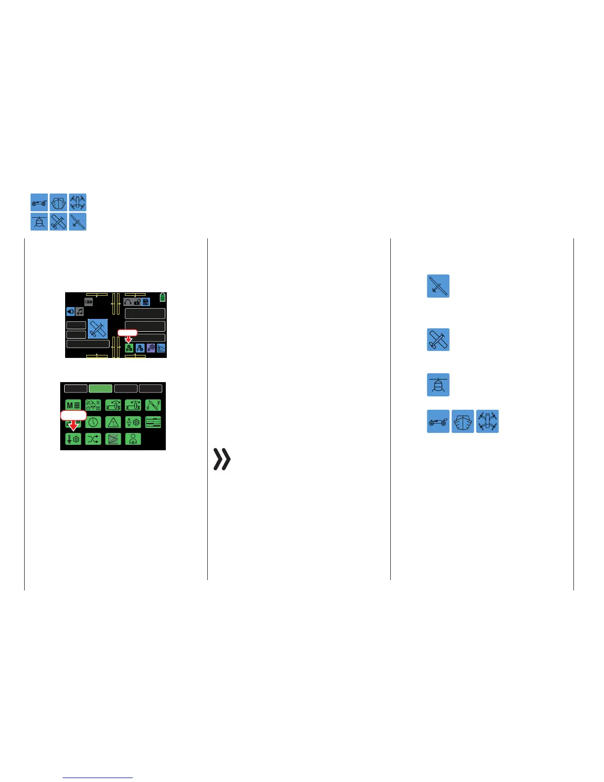
From the BASE submenu display, press the CTL Set
icon:
BACK
SYSTEM
BASE
FUNCTION
Model Sel
E.P.A
Model Type
REV/SUB
THR.CUT
Timer
TX ctl
Fail Safe
Trim Step
Servo
Out.Swap
CTL Set
Announce
Telemetry
Press
Across the top of the mz-24 Pro HoTT transmitter are
the dials and switches for servos responding to con-
trol functions 1 - 4 and their trim controls:
• 1 two-position switch with long handle (S6)
• 1 three-position switch with long handle (S3)
• 4 three-position switches with a short handle (S1,
S4, S5 and S7)
• 2 one-side, self-neutralizing three-position switch-
es with long handle (S2 and S8)
• 2 INC/DEC buttons (DT1 and DT2)
• 2 rear proportional sliders (SL1 and SL2)
• 4 proportional dials (DV1 - DV4)
By contrast, a new model memory for a helicopter
model for servo 6, the aforementioned control ele-
ments are initially inactive.
Only the servos controlled by the two control sticks
can be moved when these systems are initially deliv-
ered and a new model memory is initialized and bound
to the receiver. By contrast, the servos connected to
different slots remain in their middle position.
Though inconvenient, it is the only way to freely se-
lect from the other control elements of the transmit-
ter and avoid the deactivation of unnecessary control
elements. Any control element not needed and acci-
dentally activated has no influence on the model if it is
not assigned to any function.
Use the CTL Set submenu to assign all of the afore-
mentioned control elements as needed within any
function input without restriction. Each of these control
elements can be simultaneously assigned to several
functions as needed. For example, the same toggle
switch assigned to an input in the CTL Set submenu
can also be assigned as a timer on/off switch in the
Timer submenu, etc.
Notices
• When assigning several functions to the same
switch, note that incorrect responses may
arise, i.e. using the same switch to change
Phases and control Phase Trimming. To rem-
edy the overlap, change switch assignments
for one of the conflicting functions.
• Setting the control travel affects all outgoing
mixing and coupling functions. All servos that
are activated by the relevant control element
will be affected.
• Control direction of a glider’s brake
control, generally the "front" position
of the CH1 control stick, is defined
through the off-set value in the BUTTERFLY
OFF line of the FUNCTION submenu BUT-
TERFLY (page 202).
Conversion of a motor powered
model’s control direction of the throt-
tle control stick (CH1) is described in
the FUNCTION submenu THR.CRV (page
128).
Conversion of a helicopter’s control
direction of the throttle/pitch control
stick (CH1) is described in the FUNC-
TION submenu PIT.CRV (page 160).
Conversion of a car,
boat or drone control
direction of the throt-
tle control stick (CH1) is described in the
FUNCTION submenu THR.CRV (page 128).
90 Base menu - Control/switch setting

 Loading...


