Transmitter Start Up
Preliminary Remarks
The Graupner-HoTT system allows more than 200
models or remote-control systems to be operated at
the same time, though in practice this number will be
significantly less since permits are required for com-
bined remote operation within the 2.4 GHz ISM band.
Ultimately, however, the only thing limiting pilots is the
size of the flying field.
Battery Charged?
The battery delivered with the transmitter is only par-
tially charged. Charge it according to the charge in-
structions in Part 1 of the manual. If not fully charged,
a warning signal will sound once the voltage drops
below a certain threshold. To change the voltage set-
ting, adjust the value in the "Batt warning" line in the
SYSTEM submenu Etc.Set (page 212).
TX VOLT
04
3.5V
AUTO LOAD
RX VOLT
00
4.9V
STRENGTH
00
000%
ESC CUR
00
000.0A
ESC VOLT
00
00.0V
STRENGTH ALARM
BACK
CLR
OFF
OFF
Transmitter Startup
Whenever the transmitter is switched on, the servo
outputs on channels 1 through 12 are checked. For
safety reasons, the RF module will remain off to avoid
accidental motor starts if the impulse is outside a
pre-selected bandwidth for idling.
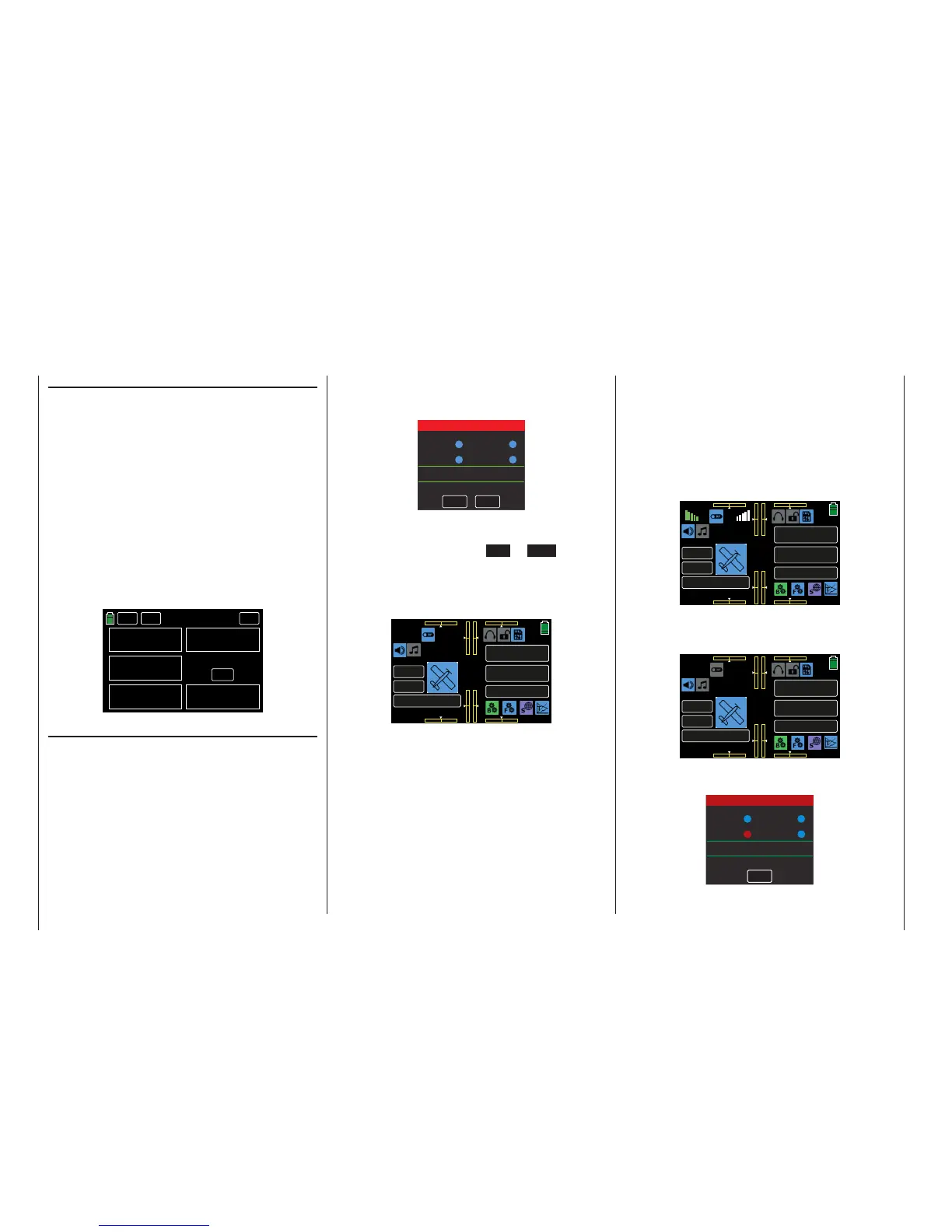
When the transmitter is turned on the RF module will
display the message:
Warning
Thr.HOLD
Thr.POS
Thr.CUT
PHASE
Please select RF ON/OFF
Normal signal
ON
OFF
Fail Safe not set
Audible warning signals will sound for a few seconds.
Either wait a few seconds until the display automati-
cally disappears or press the ON or OFF button to
initiate or turn off the RF transmission.
The basic display menu of the mz-24 HoTT Pro trans-
mitter now appears:
000
000
000
000
mz
000%
000%
BATT TIME 00: 01: 23
MODELLNAME 1
M - 1
PHASE 1
000:00.0
000:00.0
4.2V
0:01:23
TX RX
RX 00.0V
Icon symbols are either active (highlighted blue) or in-
active (grayed out). The RF switch symbol is located
at the top left corner of the display. In this example
the symbol appears blue and is positioned between
the green "TX" and the white "RX", meaning that the
RF transmission of the transmitter is on.
The green "TX" and white "RX" to the left and right
of this switch symbol indicate that an active model
memory had once been linked to a Graupner-HoTT
receiver but is currently not detected.
Once this link is established, the field strength display
appears to the left of the green "TX" and to the right
of the white "RX", and a numeric display underneath
shows the current voltage of the receiver power sup-
ply. For example:
000
000
000
000
mz
000%
000%

 Loading...


