Butterfly
Glider Braking System Adjustment
This submenu option is not available for certain model
types and configurations.
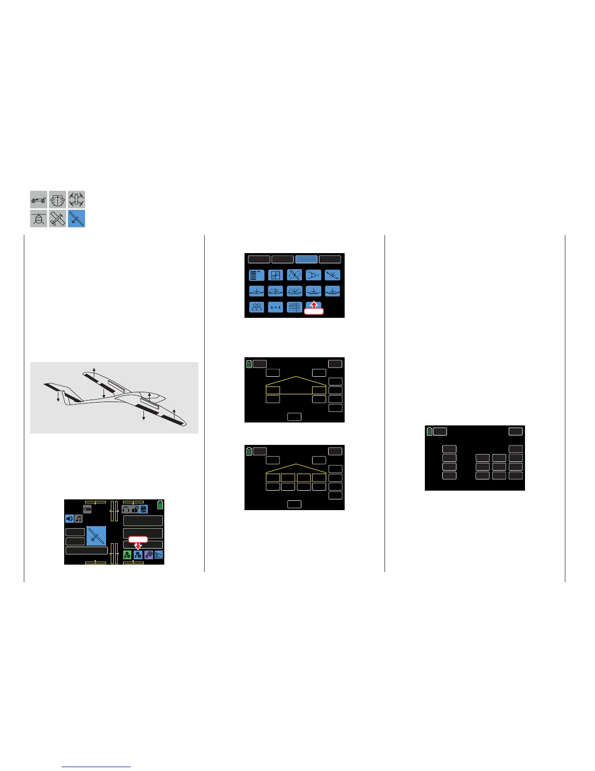
Use this menu to set aspecialbreaking flap arrange-
ment: the crow or butterfly position. In this braking
position, both ailerons are moved slightly upward,
and the flapsmove downward as far as possible. By
means of an additional mixer (the “elevator curve”
mixer described below), the elevator is trimmed so
that the flight speed does not change significantly in
comparison to the normal flight position. Otherwise,
there is a danger that the model will slow down too
much and, after the brake system is retracted (for
example to lengthen a landing approach that is too
short), will crash or fall.
This interaction of the flaps, aileron and elevatorcon-
trol the gliding angle when approaching a landing.
(The butterfly flap position is frequently used in sports
models instead of brake flaps or spoilers).
To adjust these settings, from the main display press
the FUNCTION menu gear icon (blue “F”) to bring up
the FUNCTION submenu screen:
000
000
000
000
mz
000%
000%
BATT TIME 00: 01: 23
Soarmaster
M - 4
PHASE 1
000:00.0
000:00.0
4.2V
0:01:23
Press
From the FUNCTION submenu, press the Butterfly
icon:
BACK
SYSTEM
BASE
FUNCTION
Phase
Wing MIX
D/R,EXP
Snap roll
Prog.MIX
Aile diff
Flap MIX
Flap set
Trainer
Butterfly
Sequence
Logical sw
V-Tail
THR.CRV
Press
The display shows different views depending on the
selected number of ailerons and flaps. This exam-
ple shows the display for setting a minimum, such as
2AILE:
BACK
PHASE 1 Butterfly
SERVO
INC
RES
DEC
000%
000%
INH
ACT CTL
NEXT
ON
RATE
BUTTERFLY OFF
+100%
000%
AILE1 AILE2
This example shows the display for setting a maxi-
mun, such as 4AILE4FLAP:
BACK
PHASE 1 Butterfly
SERVO
INC
RES
DEC
000%
000%
INH
ACT CTL
NEXT
ON
RATE
BUTTERFLY OFF
+100%
000%
FLAP3
FLAP4
FLAP1 FLAP2
000%
000%
Phase-Dependent Settings
This submenu allows for different phase-specific val-
ues to be programmed. Phase names are displayed
in green in the upper left side of the screen next to
the BACK button. Standard default naming for the
phases are usually displayed as NORMAL/PHASE
1. (Additional phases will be named numerically, e.g.
Phase 2, Phase 3, etc.) To define multiple phases,
refer to the FUNCTION submenu Phase section (page
120). Each new phase will need to be assigned to a
different switch. To change the phases, activate the
corresponding switch(es).
Programming
The butterfly mixers described below are actuated by
the throttle/brake control stick, assigned by default to
the CH1 input (or alternately by any other transmitter
control element that is assigned to the CH1 input of
the BASE submenu CTL Set).
In most cases, the selection is limited to preset con-
trol, and the airbrake is operated using the non-cen-
tralizing CH1 control stick:
CH 1.
CH 2.
CH 3.
CH 4.
ST 1
ST 2
ST 3
ST 4
INC
RES
DEC
+100%
+100%
+100%
+100%
+100%
+100%
CTL
– Travel+
NEXT
BACK
SERVO
CTL Set
PHASE 1
OFFSET
The use of other control elements offers the possibil-
ity of being able to control the airbrakes alternatively
through another accessory function control. This is
useful if the CH1 control stick is going to be used for
other functions.
202 Function menu | Airplane models - butterfly

 Loading...


