This function allows two switches, controls and/or log-
ical switches (or any combination thereof) to be inter-
connected in an AND or OR switch. Logical switches
activate when certain conditions are met: two switch
conditions must be met to activate an AND switch;
conversely, functions can activate an OR switch if one
of two conditions are met.
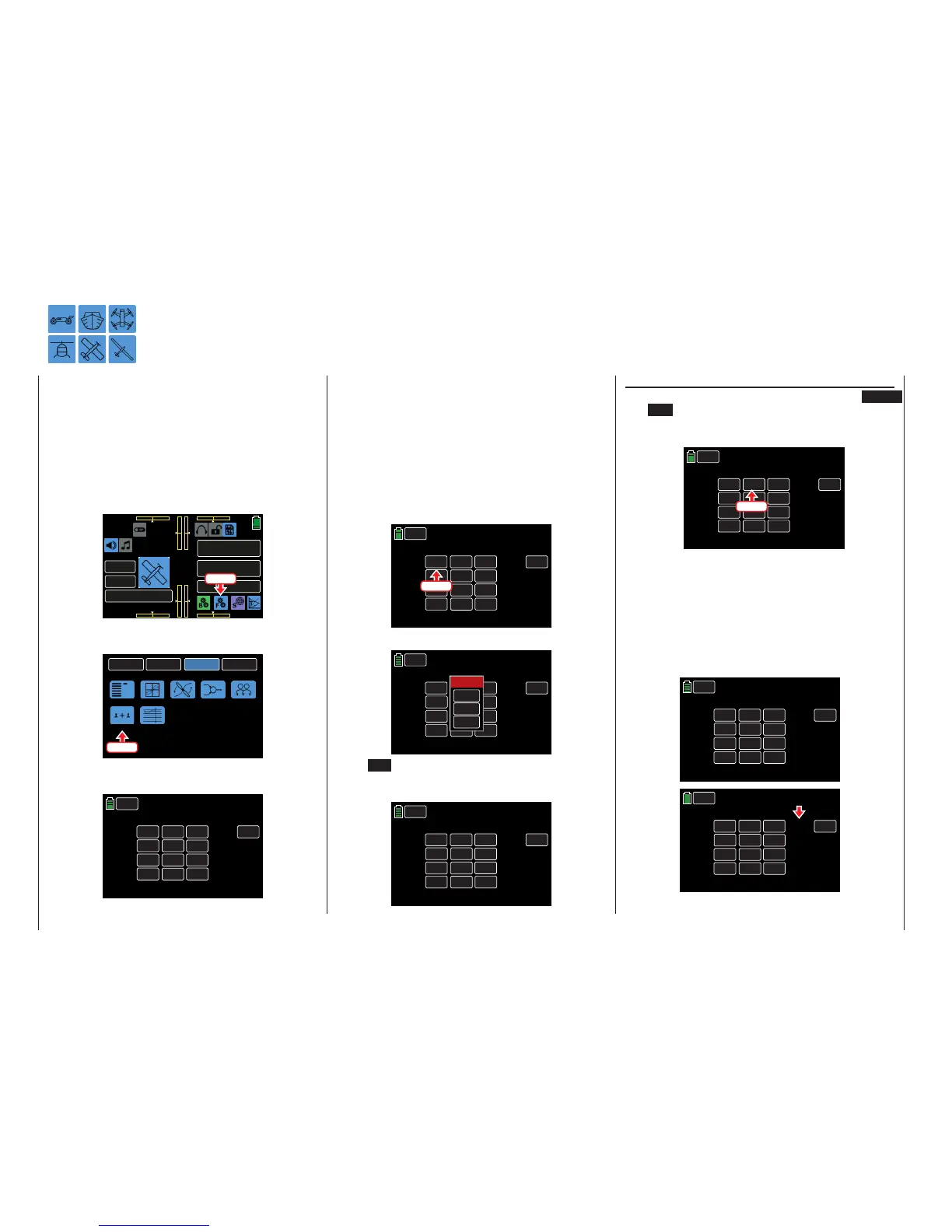
To setup a logical switch, from the main display press
the FUNCTION menu gear icon (blue “F”) to bring up
the FUNCTION submenu screen:
000
000
000
000
mz
000%
000%
BATT TIME 00: 01: 23
MODELLNAME 1
M - 1
PHASE 1
000:00.0
000:00.0
4.2V
0:01:23
Press
From the FUNCTION submenu display, press the
Logical sw icon:
BACK
SYSTEM
BASE
FUNCTION
Phase
D/R,EXP
THR.CRV
Prog.MIX
Trainer
Sequence
Logical sw
Press
A total amount of 8 logical switches, L1 - L8, can be
programmed:
BACK
Logical sw
NEXT
L1
NULL
L2
NULL
L3
NULL
L4
Logical switches
AND
AND
AND
AND
NULL
NULL
NULL
NULL
OFF
OFF
OFF
NULL
OFF
Logical Switch
Logical Switch Setup
The result of a logical switch is that it can be used as
alternative switch function. The ON/OFF column in
the display shows when the switch function has been
activated.
Programming
Assigning the required switch for a logical connection
is performed with both value fields on one line. Press
the left value field of the appropriate line to assign
switches. In the example below, switches S6 and S3
need to be assigned to L1:
BACK
Logical sw
NEXT
L1
NULL
L2
NULL
L3
NULL
L4
Logical switches
AND
AND
AND
AND
NULL
NULL
NULL
NULL
OFF
OFF
OFF
NULL
OFF
Press
An active window appears:
BACK
Logical sw
NEXT
L1
NULL
L2
NULL
L3
NULL
L4
Logical switches
UND
UND
UND
AND
NULL
NULL
NULL
NULL
OFF
OFF
OFF
NULL
OFF
Select
CLR
NO
LOGIC
Press NO to terminate the procedure.
Assign a switch following the instructions in the Con-
trol and Switch Assignment section (page 26):
BACK
Logical sw
NEXT
L1
NULL
L2
NULL
L3
NULL
L4
Logical switches
AND
AND
AND
AND
SW 3
NULL
NULL
NULL
OFF
OFF
OFF
SW 6
OFF
AND / OR
Changing the switch connection between AND
and OR can be done by pressing the button in the
center column of the display for the appropriate logi-
cal switch line:
• AND
A logical switch is activated only when both
switches are activated.
• OR
A logical switch is activated when one of the two
assigned switches activated.
The actual switch position of the logical switches is
displayed in the right column:
BACK
Logical sw
NEXT
L1
NULL
L2
NULL
L3
NULL
L4
Logical switches
AND
AND
AND
AND
SW 3
NULL
NULL
NULL
OFF
OFF
OFF
SW 6
OFF
BACK
Logical sw
NEXT
L1
NULL
L2
NULL
L3
NULL
L4
Logical switches
AND
AND
AND
AND
SW 3
NULL
NULL
NULL
OFF
OFF
OFF
SW 6
ON

 Loading...


