The transmitter’s main display is used for both oper-
ating functions and to graphically display telemetry
data. Some of the telemetry data, such as battery
voltage, appears on the main display. Additional te-
lemetry information can be found in the TELEMETRY
menu display.
To view telemetry data, press the TELEMETRY icon
(blue “T”) to bring up the TELEMETRY display screen:
000
000
000
000
mz
000%
000%
BATT TIME 00: 01: 23
MODELLNAME 1
M - 1
PHASE 1
000:00.0
000:00.0
4.2V
0:01:23
Press
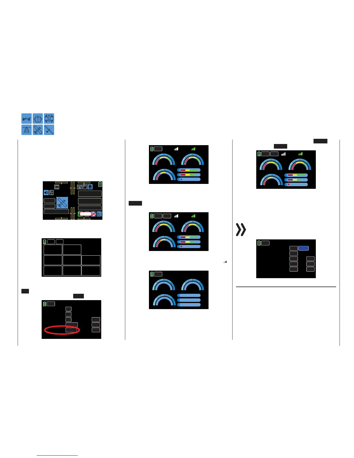
The Telemetry display has no submenu icons but has
differing screens depending on system settings. By
default, the receiver display appears:
RX
-41dB
Receiver
BACK
NEXT
TX
-62dB
VOLT
04.1V
Min V
04.1V
TEMP
+032°C
QUA
100%
STR
100%
L-PACK
2000ms
Note this display will only appear if the Outdoor disp
function of the SYSTEM submenu Display is turned
ON . If no sensors are connected to the receiver and
the Outdoor disp option is OFF (as shown below):
Display
BACK
Backlight o
Touch sense
Logo color
Outdoor disp
RFID
OFF
1
DEFAULT
OFF
Brightness
15
AAAAA876
INC
RES
DEC
Telemetry Data Display
Then the display will appear as follows:
BACK
5.2V
VOLT
5.0V
L-VOLT
3.0 3.0
R
25
6.0 6.0
0 0
70
-20
+26°C
TEMP
- 58dB
- 52dB
T
0020ms
L
075%
S
100%
Q
If at least one sensor has been connected to the re-
ceiver before the receiver is switched on, the transmit-
ter scans the sensor(s) for approx. 30 seconds. The
SRCH button appears in the upper left corner of the
display during the search process:
BACK
5.2V
VOLT
5.0V
L-VOLT
3.0 3.0
R
25
6.0 6.0
0 0
70
-20
+26°C
TEMP
- 58dB
- 52dB
T
0020ms
L
075%
S
100%
Q
SRCH
If the receiver is not within range or goes undetected,
then no search button or field strength indicators ( )
will be visible along the top of the display screen:
R
T
BACK
00.0V
VOLT
00.0V
L-VOLT
3.0 3.0
25
6.0 6.0
0 0
70
-20
000°C
TEMP
00dB
00dB
0000ms
L
000%
S
000%
Q
Turn on the receiver, or bind a receiver to the active
model memory. Refer to the BASE submenu TX ctl
(page 68) for more information on binding.
Once the sensors search is complete, the SRCH but-
ton will change to a NEXT button:
BACK
5.2V
VOLT
5.0V
L-VOLT
3.0 3.0
R
25
6.0 6.0
0 0
70
-20
+26°C
TEMP
- 58dB
- 52dB
T
0020ms
L
075%
S
100%
Q
NEXT
Tip
Refer to the RECEIVER section (page 226) for more
information on this display.
Notice
Functions of this menu operate independently
from settings in the RX SELECT line of the BASE
submenu Telemetry:
BACK
RX SELECT
SETTING & DATA VIEW
SENSOR
RF STATUS VIEW
VOICE TRIGGER
RX1
>>
>>
>>
>>
INC
RES
DEC
ALWAYS
Telemetry
Sensor(s)
A receiver operated by telemetry can support a com-
bination of up to four connected sensors.
Sensor data is only displayed to the graphs described
below if they are properly connected to before the
receiver is turned on, after all involved components
have been switched on and after all back channels are
recognized by the transmitter.
225
Telemetry data display

 Loading...


