Also make sure the relevant receiver is bound in the
BIND ON/OFF line of the BASE submenu Tx ctl, the
transmitter is set in the TX OUT SET line of the same
submenu, and that the receiver selected is turned on
in the RX SELECT line of the BASE submenu Telem-
etry. If another receiver has been selected, only the
data from the selected receiver is displayed in the Re-
ceiver display.
Sensors in the SETTING & DATA VIEW line of the
BASE submenu Telemetry will only respond under
the above prerequisites corresponding to the instruc-
tions for the respective sensor.
To switch between the displays of all automatically
activated sensors, press the NEXT button at the top
edge of the display:
BACK
5.2V
VOLT
5.0V
L-VOLT
3.0 3.0
R
25
6.0 6.0
0 0
70
-20
+26°C
TEMP
- 58dB
- 52dB
T
0020ms
L
075%
S
100%
Q
NEXT
Press
000000rpm
RPM
00000mAh
mAh
100000 15000
QUA 100
40.0 150.0
200000 30000
0 0
80.0
300.0
0 0
00.0V
BAT T
000.0A
AMP
0000m
ALT
BACK
NEXT
Continue pressing NEXT to view subsequent sensor
displays:
m/s -000.1m/s
CURRENT
QUA 100
000.0A
40.0
80.00
0000m
ALT
VOLT
00000mAh
00.0V
60.020.0
CAPACITY
m/3s 000m/3s
BACK
NEXT
RPM 000000
Tip
Further information on the modulescited below can be
found in the Appendix (page 234) and on the Internet
atwww.graupnerusa.com.
RECEIVER
BACK
5.2V
VOLT
5.0V
L-VOLT
3.0 3.0
R
25
6.0 6.0
0 0
70
-20
+26°C
TEMP
- 58dB
- 52dB
T
0020ms
L
075%
S
100%
Q
NEXT
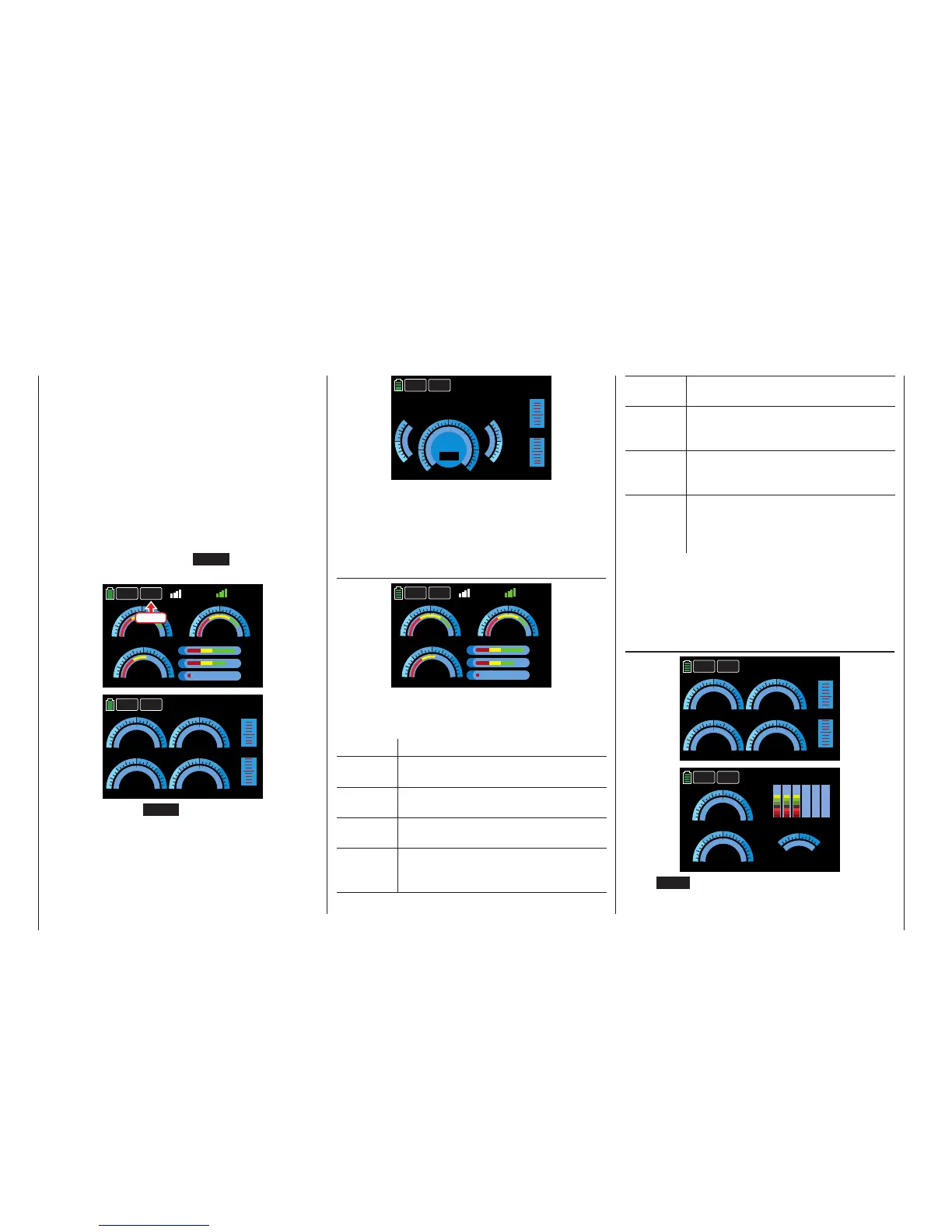
This display graph shows data from the SETTINGS
& DATA VIEW line of the BASE submenu Telemetry.
Value Explanation
R - dB Decibel level (in percent) of the trans-
mitter signal arriving at the RECEIVER
T - dB Decibel level (in percent) of the receiver
signal arriving at the TRANSMITTER
VOLT Power level (in volts) of the currently
operating receiver power supply
L-VOLT Lowest operating voltage (in volts) of
thereceiver power supply since the
last startup
TEMP Temperature (in Celsius) of the current-
ly operating receiver
Q Signal package quality (in percent) of
the data sent from the transmitter arriv-
ing at the receiver
S Signal strength (in percent) of the
transmission from the transmitter arriv-
ing at the receiver
L Shows the longest time (in millisec-
onds) data packets are lost during a
transmission from the transmitter to
receiver
Tip
For additional information on the values mentioned
above, refer to the Detailed explanations of the SET-
TINGS & DATA VIEW section (page 101).
GENERAL MODULE
000000rpm
RPM
00000mAh
mAh
100000 15000
QUA 100
40.0 150.0
200000 30000
0 0
80.0
300.0
0 0
00.0V
BAT T
000.0A
AMP
0000m
ALT
BACK
NEXT
00.0V 00.0V
1-BAT-2
BAT 1
80.0
m/s -000.2m/s m/3s 000m/3s
70
100
0
0
3.0V
-20
0.0
-20
0
-020°C -020°C
1-TEMP-2
00000ml
FUEL
2525
40.0
40.0
50
0.0
0.0
3.8
3.8
3.7
4.2V
BACK
NEXT
Press NEXT to switch between screen displays.
226 Telemetry data display

 Loading...


