BATT TIME 00: 01: 23
Starlet
M - 3
PHASE 1
000:00.0
000:00.0
4.2V
0:01:23
Press
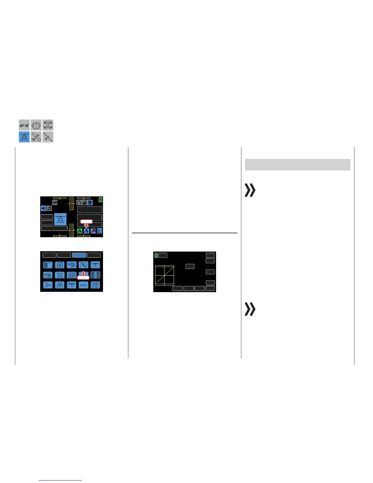
From the FUNCTION submenu display, press the
THR.CRV icon:
BACK
SYSTEM
BASE
FUNCTION
Phase
S.Limit
D/R,EXP
THR.CRV
Gyr/Gover
Swash
THR.HOLD
PIT.CRV
S.MIX
THR.MIX
Trainer
Prog.MIX
Logical sw
PIT>>TAIL
Sequence
Press
A curve mixer is available in every flight phase for
pitch curve settings. However, linear mixers cannot
be programmed for actions analog to the control stick
travels.
Phase-Dependent Settings of the Throttle Curve
This submenu allows for different phase-specific val-
ues to be programmed. Phase names are displayed
in green in the upper left side of the screen next to
the BACK button. Standard default naming for the
phases are usually displayed as NORMAL/PHASE
1. (Additional phases will be named numerically, e.g.
Phase 2, Phase 3, etc.) To define multiple phases,
refer to the FUNCTION submenu Phase section (page
120). Each new phase will need to be assigned to a
different switch. To change the phases, activate the
corresponding switch(es).
Tips
• The Throttle setting for the autorotation phase is
described in the FUNCTION submenu THR.HOLD
(page 170).
• If the THR.Limit (page 94) has been activated in
the BASE submenu CTL Set by assigning a switch
control, the previously assigned numerical value is
displayed in the THR.Limit line.
Throttle Curve
The throttle control curve can be specified by up to 7
points (termed “support points”) along the entire con-
trol stick travel:
PHASE 1
SERVO
THR.CRV
BACK
IN
OUT
POINT
OFF
INC
ENT
DEC
Y-axis
TRIM
X-axis
ST OFF
CURVE
–100%
–100%
000%
L
THR.Limit OFF
During initial setup, fewer support points are required
to set a throttle curve. However, it is recommended to
start with at least three support points.
These three endpoints describe the linear characteris-
tic of a throttle control curve: the two endpoints Throt-
tle low (L = -100% control travel) and Throttle high (H
= +100% control travel) and the control (placed in the
center).
Support points can be set, changed and deleted in
the same manner as described in the previous sec-
tion, PIT.CRV (page 154). First specify the throttle
curve using three points: the two end points L and H,
and the control (center) point. This synchronizes the
motor performance curve with the pitch curve.
Gas Motor / Electric Drive Helicopters With
Speed Controller
Notice
Refer to the Helicopters with Governor section
(page 161) for appropriate throttle curve adjust-
ment to helicopters equipped with a governor.
This setting only refers to the control curve for the
throttle servo or the speed controller.
• The control curve should be set so that the carbu-
rettor is completely open when the throttle/pitch
control stick is in end position, or the actuator of
an electric helicopter is fully enabled (with the ex-
ception of autorotation flight).
• For the hovering point (normally in the center of
the control), the carburettor setting or performance
control of the motor control unit needs to be coor-
dinated with the pitch curve to produce the desired
system speed.
• At the minimum position of the throttle/pitch con-
trol stick, initially set the throttle curve so that a
gas motor runs significantly faster in comparison
to idling, and the clutch engages reliably.
Notice
Bothgas enginesand electric motorsare stopped
using the THR.Limit within the phase.
It is unnecessary to program twophases, "with
throttle preset" and"without throttle preset" to phase
a gas preset,as is sometimes used in other remote
control systems. The mz-24 Pro transmitter allows
the system speed to be increased below the hover-
ing point much more flexibly andsensitivelywith the
THR.Limit than by using a gas preset.
160 Function menu | Helicopter model - Throttle curve

 Loading...


