BATT TIME 00: 01: 23
MODELLNAME 1
M - 1
PHASE 1
000:00.0
000:00.0
4.2V
0:01:23
TX RX
RX 00.0V
Warning
Thr.HOLD
Thr.POS
Thr.CUT
PHASE
Please Select RF ON/OFF
ON
RC Signal
OFF
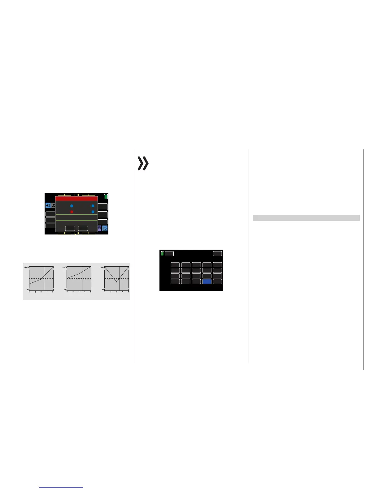
The following three diagrams show typical 3-point
throttle curves for different phases such as hover-
ing,aerobatics and 3-D flight.
Example Throttle Curves for Different Phases:
Control travel
Hover
Control travel
Aerobatics
Control travel
3D
Output
Output
Output
Notices
• Use the Throttle Limit Function (page 94)
of the BASE submenu CTL Set. The throt-
tle servo is normally completely separate from
the throttle curve at the left-stop of the pro-
portional dial DV1 (throttle limiter); the motor
is idling and only reacts to CH1 trimming. This
option allows you to start the motor from any
phase and turn it off using digital trimming.
After starting the motor,slowly turn the throt-
tle limiter to the opposite right-stop in order
tocompletely actuate the throttle servousing
the throttle/pitch control stick. To keep the
throttle servo from being limited by the throttle
limiter in the full throttle direction, use CH12
in the FUNCTION submenu D/R,EXP to set
the control travel value on the Travel+ column
according to each phase to +125 %:
CH 9.
CH 10.
CH 11.
CH 12.
NONE
NONE
NONE
NONE
INC
RES
DEC
+100%
+100%
+100%
+100%
+125%
+100%
CTL
– Travel +
NEXT
BACK
SERVO
CTL Set
PHASE 1
OFFSET
0%
0%
0%
0%
+100%
+100%
• Since electric drives do not require an idle
setting, when making the basic settings for
an electric helicopter, ensure that the control
range of the throttle limiter reliably exceeds
or falls below the setting range of the motor
control unit, normally extending from -100%
to +100%.
The Travel setting of the throttle limiter may
have to be adapted in each phase by chang-
ing the value in the CH12 line of the FUNC-
TION submenu D/R,Exp.
The throttle curve should be adapted in the
same manner as with a gas helicopter in flight.
Tip
In order to measure the flight time of a (gas) helicopter,
assign a control switch to the throttle limit servo and use
it to start/stop a Timer (page 74).
Helicopters with Governor
In contrast to speed controllers that only regulate
performance like a carburetor, governors maintain a
constant speed in the system that they are monitor-
ing by independently regulating the provided output.
With gas helicopters, the control independently con-
trols the throttle servo like the motor control unit of an
electric helicopter. Therefore, governors only require
a speed setting and not a classic throttle curve. A de-
viation from the set speed occurs when the required
output exceeds the maximum available output.
Normally, receiver output 8 is used for connecting a
governor. Refer to Receiver Configuration - Heli-
copter Models (page 31) for additional information.
Do not use the gas throttle limiter on output 8, since it
exclusively acts via the Throttle Curve mixer on out-
put 6, which is not assigned.
In order to take advantage of the comfort and safety
features of the throttle limiter, connect the governor
to receiver output 6 (this is different from the general
connecting strategy). Only adapt the throttle curve so
that it can assume the task of a normal servo.
161
Function menu | Helicopter model - Throttle curve

 Loading...


