End Point Adjustments allows definition of the maxi-
mum servo travel for any channel. This feature is help-
ful with components, such as wing flaps, that may get
damaged by excessive movements.
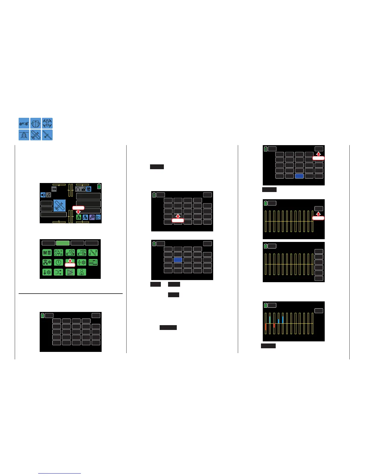
To set the E.P.A, from the main display press the BASE
menu gear icon (green "B") to bring up the BASE sub-
menu screen:
000
000
000
000
mz
000%
000%
BATT TIME 00: 01: 23
MODELLNAME 1
M - 1
PHASE 1
000:00.0
000:00.0
4.2V
0:01:23
Press
From the BASE submenu display, press the E.P.A
icon:
BACK
SYSTEM
BASE
FUNCTION
Model Sel
E.P.A
Model Type
REV/SUB
THR.CUT
Timer
TX ctl
Fail Safe
Trim Step
Servo
Out.Swap
CTL Set
Announce
Telemetry
Press
E.P.A. Adjustment
In the E.P.A display, the parameters are set as they
relate to the servo, i.e. the servo path and angle of
rotation or its limit.
BACK
CH 1.
CH 2.
CH 3.
CH 4.
CH 5.
150%
150%
150%
150%
150%
INC
RES
DEC
100%
100%
100%
100%
100%
100%
100%
100%
100%
150%
150%
150%
150%
150%
100%
E.P.A
– Limit Limit +
– Travel +
NEXT
SERVO
E.P.A
Setting the E.P.A
The set values always correspond to the settings in
the BASE submenu REV/SUB.
Tip
Press the NEXT button on the right side of the display
to scroll through the channel screens.
To change a value, press the desired button. In the
example below, Channel 3 Travel:
BACK
CH 1.
CH 2.
CH 3.
CH 4.
CH 5.
150%
150%
150%
150%
150%
INC
RES
DEC
100%
100%
100%
100%
100%
100%
100%
100%
100%
150%
150%
150%
150%
150%
100%
E.P.A
– Limit Limit +
– Travel +
NEXT
SERVO
Press
The field highlights blue:
BACK
CH 1.
CH 2.
CH 3.
CH 4.
CH 5.
150%
150%
150%
150%
150%
INC
RES
DEC
100%
100%
100%
100%
100%
100%
100%
100%
100%
150%
150%
150%
150%
150%
100%
E.P.A
– Limit Limit +
– Travel +
NEXT
SERVO
Press the INC or DEC button at the right edge of
the display to increase/decrease the value of the ac-
tive field. Press the RES button to reset the changed
value back to the default. Alternatively, press the ar-
row keys ( pq ) to the left of the display screen to
achieve the same result.
Use the same procedure for all settings.
To advance directly to the BASE submenu Servo dis-
play, press the SERVO button in the top right corner
of the screen. Alternatively, simultaneously press the
arrow keys ( pq ) to the left of the display (while no
fields are highlighted) to also bring up the Servo dis-
play:
BACK
CH1
CH2
CH3
CH4
CH5
150%
150%
150%
150%
150%
INC
RES
DEC
104%
111%
107%
077%
088%
097%
88%
115%
111%
150%
150%
150%
150%
150%
076%
E.P.A
– Limit Limit +
– Travel +
NEXT
SERVO
Press
Press the TEST button to activate the Servo Test
function (page 87):
BACK
TEST
NORMAL
1 2 3
4
5 6
7
8 9
10
11
12
000%
000%
000%
000%
000%
000%
000%
000%
000%
000%
000%
000%
Servo
Press
BACK
NORMAL
1 2 3
4
5 6
7
8 9
10
11
12
000%
000%
000%
000%
000%
000%
000%
000%
000%
000%
000%
000%
Servo
VIEW
+0.5s
INC
RES
DEC
START
Upon activating one or more control elements of the
transmitter, the resulting servo travel is graphically
displayed, as shown below:
BACK
TEST
NORMAL
1 2 3
4
5 6
7
8 9
10
11
12
000%
000%
000%
000%
000%
000%
000%
–100%
+100%
–061%
+061%
+100%
Servo
Press the BACK button to return to the E.P.A display
screen.
62 Base menu - Servo path/Servo limit

 Loading...


