Programming Example
Phase-Specific Flaps Trimming
The following example shows how to correct the
trimming of the phase-specific (and recallable) flaps
trimming through only one control element in all the
phases.
To understand this programming example make sure:
individual menu descriptions are read and under-
stood, be familiar with basic transmitter use, perform
the fixed-wing Receiver Configuration according to
the instructions (page 32), completely program the
model into the transmitter, mechanically adjust the
controls and understand the correct lateral deflec-
tion of all rudders. It helps, but does not hinder, if the
model has already performed test flights and received
the resulting adjustments.
Programming
Turn on the transmitter and start programming the
flaps positions in the BASE submenu Trim Step.
Trim Step
BACK
PHASE 1
SERVO
T1
STEP
POS
SET
D.TRIM 1
T4
INC
RES
DEC
04
000%
000%
04
000%
NONE
NONE
04
04
T2 T3
000%
000%
000%
000%
000%
D.TRIM 2
SET
VIEW
INH
ON
AUTO TRIM
CO
CTL
Trim Step
In one of the two D.TRIM lines press to highlight blue
the NONE| button. Press the INC or DEC buttons
or the arrow keys ( pq ) to select CH6:
BACK
PHASE 1
SERVO
T1
STEP
POS
SET
D.TRIM 1
T4
INC
RES
DEC
04
000%
000%
04
000%
CH 6
NONE
04
04
T2 T3
000%
000%
000%
000%
000%
D.TRIM 2
SET
VIEW
INH
ON
AUTO TRIM
CO
CTL
Trim Step
Back out and navigate to the FUNCTION submenu
Prog.MIX.
Prog.MIX
Bring up the desired phase.
Program the mixer numbers into the phase according
to the following schema:
• Left/Right Ailerons:
CH6 >> CH2
CH6 >> CH5
• Single Left/Right Flaps Pair:
CH6 >> CH6
CH6 >> CH7
• Second Left/Right Flaps Pair:
CH6 >> CH9
CH6 >> CH10
For a model type with 2AILE2FLAPS, reference the
“THERMAL” display example as follows:
2.
3.
4.
ON
ON
NEXT
ON
1.
ON
CH 6
CH 6
CH 6
CH 6
CH 5
CH 7
CH 6
CH 2
>>
>>
>>
>>
ACT
SLVMST
SET
5.
ON
CH 6
CH 3
>>
>>
>>
>>
>>
>>
BACK
THERMAL
SERVO
Prog.MIX
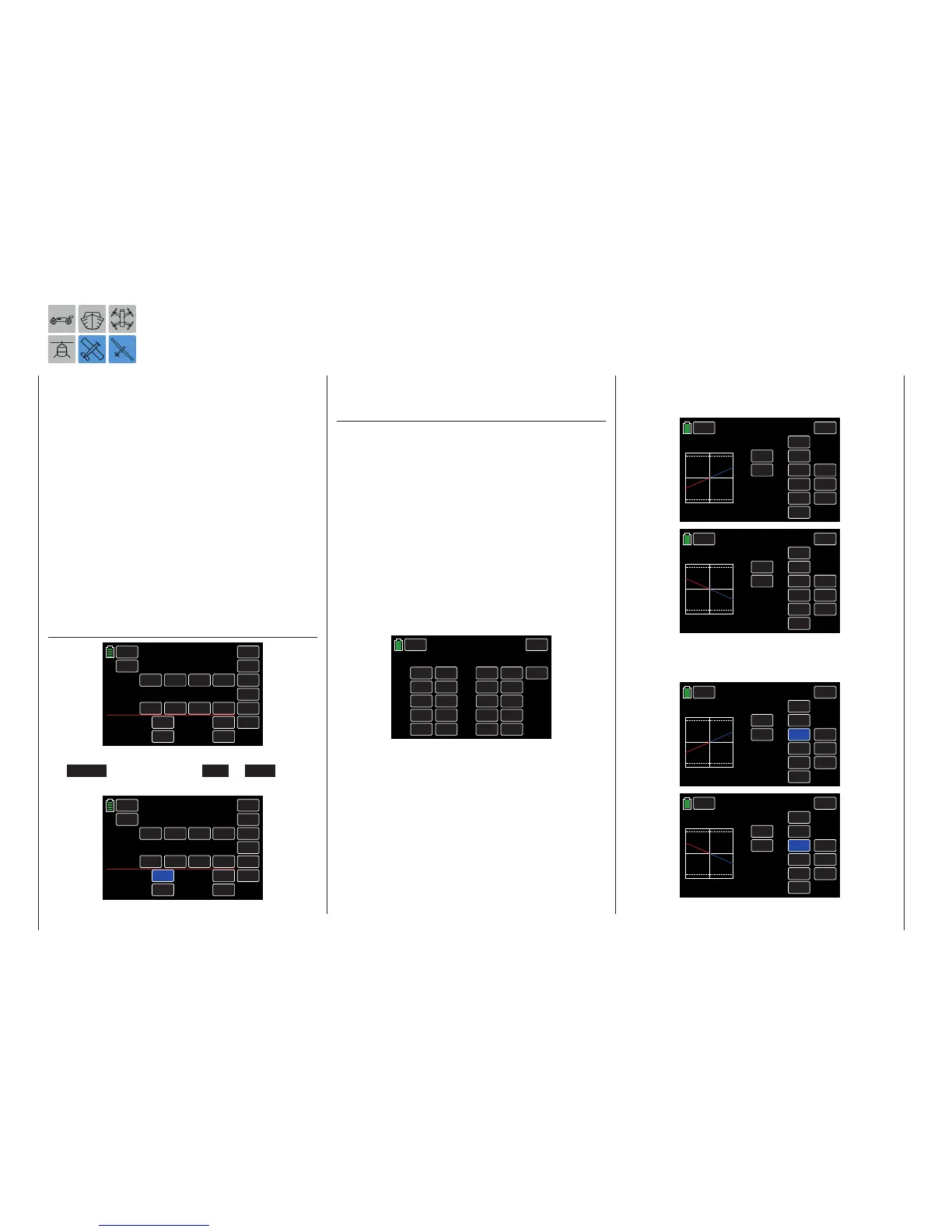
The mixing direction of the individual mixer pairs may
need to be set individually, depending on the wing
servos installation situation and the desired operating
direction of the selected digital trim button.
Individually setting mixing directions allows for con-
trasting and parallel mixing directions for each flap
pair:
CH6
A
OFFSET X
CTL
ON
000%
INC
RES
DEC
000%
CH2
>>
ACT
ON
B
OFFSET Y
+050%
+050%
BACK
THERMAL
SERVO
Prog.MIX
ON
OFF
TRIM
SYM
CH6
A
OFFSET X
CTL
ON
000%
INC
RES
DEC
000%
CH5
>>
ACT
ON
B
OFFSET Y
–050%
–050%
BACK
THERMAL
SERVO
Prog.MIX
ON
OFF
TRIM
SYM
In both cases, the trimming distance (max. 37.5% at
125% admixture) is determined according to the mix-
ing proportion:
CH6
A
OFFSET X
CTL
ON
000%
INC
RES
DEC
000%
CH2
>>
ACT
ON
B
OFFSET Y
+050%
+050%
BACK
THERMAL
SERVO
Prog.MIX
ON
OFF
TRIM
SYM
CH6
A
OFFSET X
CTL
ON
000%
INC
RES
DEC
000%
CH5
>>
ACT
ON
B
OFFSET Y
–050%
–050%
BACK
THERMAL
SERVO
Prog.MIX
ON
OFF
TRIM
SYM
230 Programming example - Flaps trimming

 Loading...


