BATT TIME 00: 01: 23
Extra 360
M - 2
PHASE 1
000:00.0
000:00.0
4.2V
0:01:23
Press
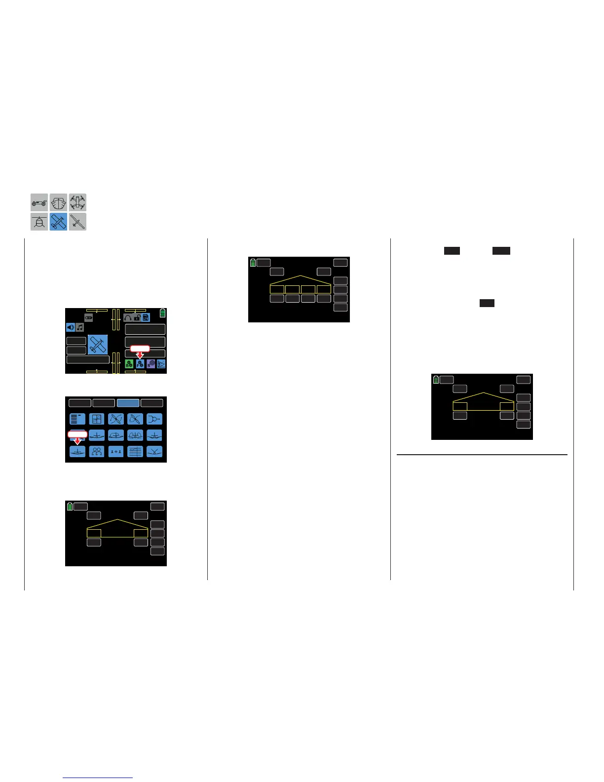
From the FUNCTION submenu, press the Airbrake
icon:
BACK
SYSTEM
BASE
FUNCTION
Phase
Wing MIX
D/R,EXPO
THR.CRV
Idle LOW
Snap roll
Prog.MIX
Aile diff
Flap MIX
Flap set
TTrainer
Airbrake
Sequence
Logical sw
V-Tail
Press
The display shows different views depending on the
selected number of ailerons and flaps. This exam-
ple shows the display for setting a minimum, such as
2AILE:
INC
RES
DEC
000%
000%
AILE1 AILE2
INH
ACT CTL
NEXT
ON
RATE
BACK
PHASE 1 Airbrake
SERVO
This example shows the display for setting a maxi-
mun, such as 4AILE4FLAP:
INC
RES
DEC
000%
000%
INH
ACT CTL
NEXT
ON
RATE
BACK
PHASE 1 Airbrake
SERVO
FLAP1 FLAP2
FLAP3
FLAP4
000% 000%
Phase-Dependent Settings
This submenu allows for different phase-specific val-
ues to be programmed. Phase names are displayed
in green in the upper left side of the screen next to
the BACK button. Standard default naming for the
phases are usually displayed as NORMAL/PHASE
1. (Additional phases will be named numerically, e.g.
Phase 2, Phase 3, etc.) To define multiple phases,
refer to the FUNCTION submenu Phase section (page
120). Each new phase will need to be assigned to a
different switch. To change the phases, activate the
corresponding switch(es).
Programming
Using either the ACT or CTL options, enter the flap
and elevator deflection direction amount for braking.
In order for these settings to be effective and retriev-
able (e.g. with a switch), program the option fields as
described below:
• ACT Line (Active)
To activate ON or inhibit INH a specific phase,
press to change the value fields on the appropri-
ate screen.
If this phase is assigned to a switch, this individu-
ally turns on and off the effect of the selected con-
trol element on the flap position for specific phases
when the value field is ON.
• CTL Line (Control/Switch)
Use this field to assign a control or control switch
to a specific phase mixer. Refer to the Control
and Switch Assignment section (page 26) for in-
formation on assigning switches. In the example
below, the phase titled LANDING is assigned to
S6:
INC
RES
DEC
000%
000%
AILE1 AILE2
ON
ACT CTL
NEXT
SW 6
RATE
BACK
LANDING Airbrake
SERVO
RATE Line
A symmetrical or an asymmetrical effect can be de-
fined for each flap pair. In order to be able to define
upward and downward deflections, the setting range
is ±150%.
Switch to the desired phase and press the value field
to be set. In the example below, the phase titled
LANDING needs the AILE1 RATE changed to +023%:
200 Function menu | Airplane models - brakes

 Loading...


