Telemetry
Settings and Displays
Receiver settings and the displays and settings of the
connected telemetry sensors can be retrieved and
programmed in real time in the Telemetry menu. The
receiver connection is maintained by the feedback
channel integrated in the HoTT receivers.
Up to four sensors can be connected through a V or Y
cable at the telemetry connection of the HoTT receiv-
ers provided with actual firmware.
The Telemetry menus can be kept current by recent
and future updates, and allow for additional functions
or languages to be added and maintained.
Tip
Automatic update notifications will be sent by e-mail
once products are registered at http://www.graupneru-
sa.com/PRODUCT-REGISTRATION_ep_56-1.html.
Notes
• The following instructions are based on
the functions available at the time this
manual was drafted.
• As noted in the Binding Multiple Receivers
section (page 69), multiple receivers can be
bound to a single model. Users can directly
manage one or two receivers per model and
use a setup menu to distribute the 12 trans-
mitter control channels between the two re-
ceivers.
During subsequent operation, only the receiv-
er selected in the line RX SELECT of the Te-
lemetry menu can establish a telemetry con-
nection between the transmitter and the most
recently bound receiver.
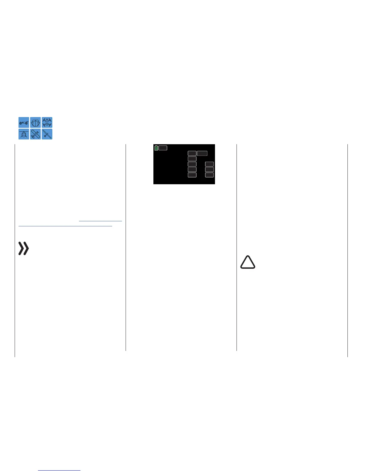
BACK
RX SELECT
SETTING & DATA VIEW
SENSOR
RF STATUS VIEW
VOICE TRIGGER
RX1
>>
>>
>>
>>
INC
RES
DEC
ALWAYS
Telemetry
Only these receivers can be addressed by
the Telemetry menu. The selection may have
to change before settings can be made to a
specific receiver. This is because the second
and subsequent receivers work in parallel in
the Slave Mode.
• The telemetry data exchange between trans-
mitter and receiver normally takes place after
the four large RC data-packs are transmitted,
resulting in a delay of control button reactions
or setting changes. This does not constitute
an error.
• When adjusting the remote control, make sure
that the transmitter antenna is a minimum
distance of 3 feet (1 meter) from the receiver
antennas. Antennas too close to one anoth-
er may cause an interruption in the feedback
channel connection.
• All settings that have been made using the Te-
lemetry menu (i.e. fail safe, servo rotation di-
rection reversal, servo travel, mixer and curve
settings, etc.) are saved in the receiver and are
only transferred to other models when the re-
ceiver is changed.
The HoTT receiver should be reinitialized be-
fore use in another model. Refer to the Re-
ceiver Start Up and Reset section (page 14)
for more information.
Only program the servo rotation direction, ser-
vo travel, mixer and curve settings, etc. in the
transmitter with the model-specified standard
menu. Settings will overlap different transmit-
ters, causing operation failure.
• Transmitter control channels can be assigned
according to personal preference within single
or multiple receivers using the receiver-side
channel assignment functioncalled Channel
Mapping (page 104). Additionally, multiple
receiver outputs can be assigned the same
control function. This is useful, for example,
if using two servos (instead of one) to actuate
each aileron, etc.
WARNING
• To avoid malfunctions from the feed-
back channel when operating towed
models, maintain a minimum distance
of approximately 20 inches (50 cm) be-
tween the participating receivers or
their antennas. Using the satellite re-
ceiver is an option.

 Loading...


