CTL Column (Control/Switch)
Assigning Switch or Control
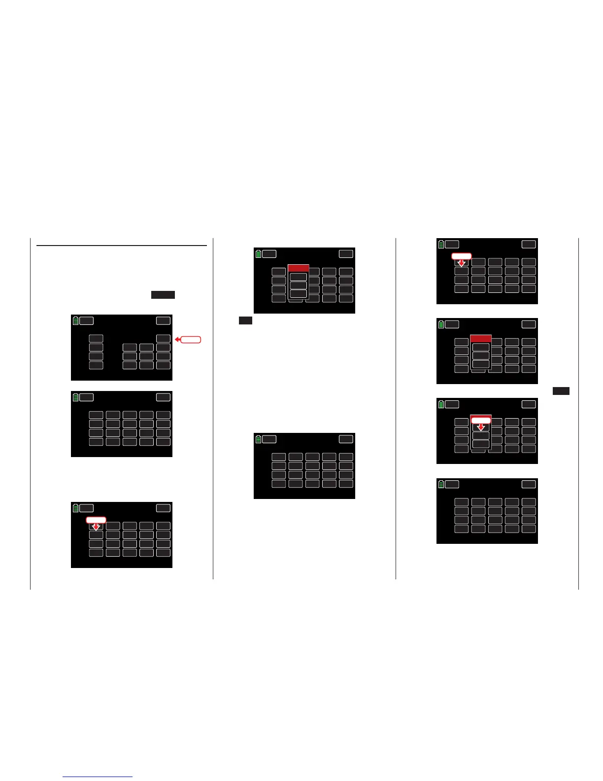
Tip
Channels 1 - 4 are located on the first page of this dis-
play screen, 5 - 8 on page 2, 9 - 12 on page three. The
delay menu is on page 4. Press the NEXT button on
the right side of the display to advance screens:
CH 1.
CH 2.
CH 3.
CH 4.
ST 1
ST 2
ST 3
ST 4
INC
RES
DEC
+100%
+100%
+100%
+100%
+100%
+100%
CTL
– Travel+
NEXT
BACK
SERVO
CTL Set
PHASE 1
OFFSET
CH 9.
CH 10.
CH 11.
CH 12.
NONE
NONE
NONE
NONE
INC
RES
DEC
+100%
+100%
+100%
+100%
+100%
+100%
CTL
– Travel +
NEXT
BACK
SERVO
CTL Set
PHASE 1
OFFSET
000%
000%
000%
000%
+100%
+100%
To assign a control element, press on the value field in
the line of the desired control channel. In the example
below, CH6 needs to be assigned to switch SL2:
CH 5.
CH 6.
CH 7.
CH 8.
NONE
NONE
NONE
NONE
INC
RES
DEC
+100%
+100%
+100%
+100%
+100%
+100%
CTL
– Travel +
NEXT
BACK
SERVO
CTL Set
PHASE 1
OFFSET
000%
000%
000%
000%
+100%
+100%
Press
The active Select window appears:
CH 5.
CH 6.
CH 7.
CH 8.
NONE
NONE
NONE
NONE
INC
RES
DEC
+100%
+100%
+100%
+100%
+100%
+100%
CTL
– Travel +
NEXT
BACK
SERVO
CTL Set
PHASE 1
OFFSET
000%
000%
000%
000%
100%
100%
Select
CLR
NO
LOGIC
Press NO to terminate the procedure.
To assign the control or switch, activate the desired
control element. Remember that the dials and rotary
controls are only recognized after a pause and need
to be activated for slightly longer than the switches.
Turn the dial in either direction to register the assign-
ment. Note that with an assigned 2-position switch,
the only option is to flip back-and-forth between the
end values (for example motor ON/OFF). The 3-posi-
tion switch offers a middle position.
The field displays either the control name or the
switch number. In the example below, CH6 has been
assigned to SL2:
CH 5.
CH 6.
CH 7.
CH 8.
NONE
SL 2
NONE
NONE
INC
RES
DEC
+100%
+100%
+100%
+100%
+100%
+100%
CTL
– Travel +
NEXT
BACK
SERVO
CTL Set
PHASE 1
OFFSET
000%
000%
000%
000%
100%
100%
Deleting Controls or Switches
Press the value field of the assignment to be delet-
ed. In the example below, the switch assigned to CH6
needs to be cleared:
CH 5.
CH 6.
CH 7.
CH 8.
NONE
SL 2
NONE
NONE
INC
RES
DEC
+100%
+100%
+100%
+100%
+100%
+100%
CTL
– Travel +
NEXT
BACK
SERVO
CTL Set
PHASE 1
OFFSET
000%
000%
000%
000%
100%
100%
Press
The active Select window reappears:
CH 5.
CH 6.
CH 7.
CH 8.
NONE
SL 2
NONE
NONE
INC
RES
DEC
+100%
+100%
+100%
+100%
+100%
+100%
CTL
– Travel +
NEXT
BACK
SERVO
CTL Set
PHASE 1
OFFSET
000%
000%
000%
000%
100%
100%
Select
CLR
NO
LOGIC
To delete the assigned control or switch, press CLR:
CH 5.
CH 6.
CH 7.
CH 8.
NONE
SL 2
NONE
NONE
INC
RES
DEC
+100%
+100%
+100%
+100%
+100%
+100%
CTL
– Travel +
NEXT
BACK
SERVO
CTL Set
PHASE 1
OFFSET
000%
000%
000%
000%
100%
100%
Select
CLR
NO
LOGIC
Press
The CH6 field returns to NONE:
CH 5.
CH 6.
CH 7.
CH 8.
NONE
NONE
NONE
NONE
INC
RES
DEC
+100%
+100%
+100%
+100%
+100%
+100%
CTL
– Travel +
NEXT
BACK
SERVO
CTL Set
PHASE 1
OFFSET
000%
000%
000%
000%
+100%
+100%
Use the same procedure for the other settings.
Press
91
Base menu - Control/switch setting

 Loading...


