Notices
• The controllers assigned in this sub-menu
globally affect all the phases. Only the offset
in the second line and the Travel Setting (third
and fourth column) affect specific phases.
• Pay attention to default receiver channel as-
signments. For example, if a model with
flaps assigns a control or switch identified
as FLAP(1L) to input 6, its function is depen-
dent on the current setting in the ACT line
of the FUNCTION submenu Flap set (page
196). If the value field to the right of the ACT
line is INH or OFF , then this control or
switchacts exclusively onservo 6 (and possi-
bly 7), whose values are set in the FUNCTION
submenu D/R,Exp (page 124).
Phase Depending Settings
The CTL Set submenu allows for phase-specific sym-
metrical delay values to be programmed in the OFF-
SET and TRAVEL columns.
Phase names are displayed in green in the upper left
side of the screen next to the BACK button. Standard
defaults naming for the phases is usually displayed
as NORMAL/PHASE 1. Additional phases will be
named numerically, e.g. Phase 2, Phase 3, etc. To
define multiple phases, refer to the FUNCTION sub-
menu Phase section (page 120). Each new phase will
need to be assigned to a different switch. To change
the phases, activate the corresponding switch(es)
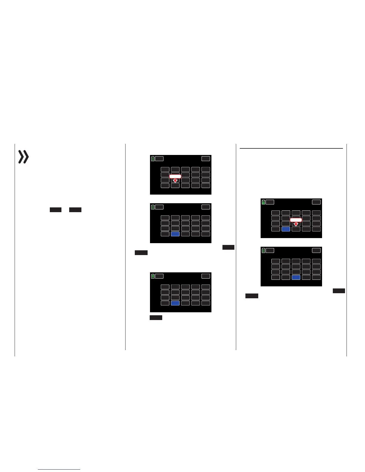
OFFSET Column
Use this column to change the center of each control
element, i.e. its zero point (or if desired with reference
to a specific phase).
Press the Offset value to be changed. In the example
below, the offset for CH8 needs to be increased:
CH 5.
CH 6.
CH 7.
CH 8.
NONE
NONE
NONE
DV 2
INC
RES
DEC
+100%
+100%
+100%
+100%
+100%
+100%
CTL
– TRAVEL+
NEXT
BACK
SERVO
CTL Set
PHASE 1
OFFSET
000%
000%
000%
000%
+100%
+100%
Press
The field highlights to blue:
CH 5.
CH 6.
CH 7.
CH 8.
NONE
NONE
NONE
DV 2
INC
RES
DEC
+100%
+100%
+100%
+100%
+100%
+100%
CTL
– TRAVEL+
NEXT
BACK
SERVO
CTL Set
PHASE 1
OFFSET
000%
000%
000%
000%
100%
100%
The adjustment range is ±125%. Press the INC
or DEC button at the right edge of the display to
increase/decrease the value. Alternatively, press the
arrow keys ( pq ) to the left of the display screen to
achieve the same result:
CH 5.
CH 6.
CH 7.
CH 8.
NONE
NONE
NONE
DV 2
INC
RES
DEC
+100%
+100%
+100%
+100%
+100%
+100%
CTL
– TRAVEL+
NEXT
BACK
SERVO
CTL Set
PHASE 1
OFFSET
000%
000%
000%
+012%
100%
100%
Press the RES button to reset the changed value
back to the default (+100%).
Use the same procedure for the other settings.
-TRAVEL+ Column
Use this column to set the travel of each control ele-
ment.
Press the left value field in the corresponding line to
set a value to the minus side ( - ) of the control travel,
and/or on the right to set a value on the plus side (
+ ) of the control travel. In the example below, both
the minus side of the travel distance needs to be de-
creased. Press the value field in the appropriate col-
umn of the Travel columns:
CH 5.
CH 6.
CH 7.
CH 8.
NONE
NONE
NONE
DV 2
INC
RES
DEC
+100%
+100%
+100%
+100%
+100%
+100%
CTL
– TRAVEL+
NEXT
BACK
SERVO
CTL Set
PHASE 1
OFFSET
000%
000%
000%
+012%
100%
100%
Press
The field highlights to blue:
CH 5.
CH 6.
CH 7.
CH 8.
NONE
NONE
NONE
DV 2
INC
RES
DEC
+100%
+100%
+100%
+100%
+100%
+100%
CTL
– TRAVEL+
NEXT
BACK
SERVO
CTL Set
PHASE 1
OFFSET
000%
000%
000%
+012%
100%
100%
The adjustment range is ±125%. Press the INC
or DEC button at the right edge of the display to
increase/decrease the value. Alternatively, press the
arrow keys ( pq ) to the left of the display screen to
achieve the same result.
92 Base menu - Control/switch setting

 Loading...


