RATE Line
A symmetrical or an asymmetrical effect can be de-
fined for each flap pair. In order to be able to define
upward and downward deflections, the setting range
is ±150%.
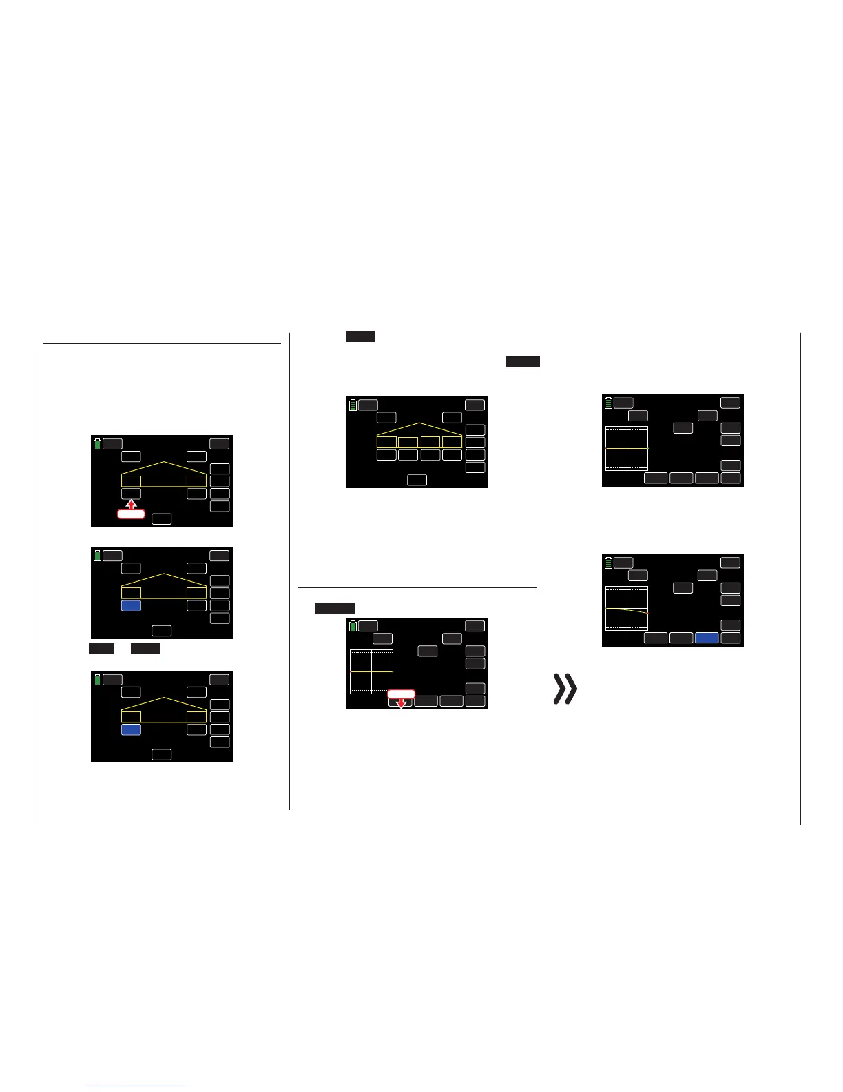
Switch to the desired phase and press the value field
to be set. In the example below, the phase titled
LANDING needs the AILE1 RATE changed to +034%:
BACK
LANDING Buttery
SERVO
INC
RES
DEC
000%
000%
ON
ACT CTL
NEXT
SW 5
RATE
BUTTERFLY OFF
+090%
+090%
AILE1 AILE2
Press
The field highlights blue:
BACK
LANDING Buttery
SERVO
INC
RES
DEC
000%
000%
ON
ACT CTL
NEXT
SW 5
RATE
BUTTERFLY OFF
+090%
+090%
AILE1 AILE2
Press the INC or DEC buttons or the arrow keys
( pq ) to increase/decrease the value:
BACK
LANDING Buttery
SERVO
INC
RES
DEC
+034%
000%
ON
ACT CTL
NEXT
SW 5
RATE
BUTTERFLY OFF
+090%
+090%
AILE1 AILE2
Use the same procedure to adjust the other values
for all remaining ailerons, including inboard ailerons.
Press the RES button to reset the changed value
back to the default.
To access the flaps setting screen, press the NEXT
button at the right edge of the display using the pro-
cedure described above:
BACK
LANDING Buttery
SERVO
INC
RES
DEC
–050%
–050%
ON
ACT CTL
NEXT
SW 5
RATE
BUTTERFLY OFF
+090%
000%
FLAP3
FLAP4
FLAP1 FLAP2
–075%
–075%
Tips for Visualizing the Braking Effect:
Spread the flaps and, from the front, look atthe surface
from above and below. The greater the projected sur-
face of the protruding rudder, the greater the braking
effect.
Elevator Curve Display
To access the control position display screen, press
the ST OFF button at the bottom left of the display:
LANDING Buttery
SERVO
BACK
IN
OUT
POINT
OFF
INC
ENT
DEC
Y-axis
X-axis
ST OFF
CURVE
+100%
000%
000%
H
SW 5
CTL
ON
ACT
NEXT
ELEV
The green, vertical bar in the graphic display indicates
the brake control position. The bar moves away from
the edge of the graph as soon as the throttle/brake
control stick is moved from its higher or lower end
point.
LANDING Buttery
SERVO
BACK
IN
OUT
POINT
OFF
INC
ENT
DEC
Y-axis
X-axis
ST ON
CURVE
+100%
000%
000%
H
SW 5
CTL
ON
ACT
NEXT
ELEV
Move the elevator curve toward the opposite stop as
needed, in direction of "brake active". The method for
adjusting the curve of this 7-point curve mixer follows
the same principles as those used for the curve mixer
described in the FUNCTION submenu THR.CRV:
LANDING Buttery
SERVO
BACK
IN
OUT
POINT
ON
INC
DEC
CURVE
+100%
–025%
–025%
H
ON
CTL
ON
ACT
NEXT
ELEV
ENT
Y-axis
X-axis
ST ON
Attention
The chosen setting should be tested and adjust-
ed at a sufficient height. Make sure that the mod-
el does not become too slow when the brake
system is extended! If this occurs, there is risk that the
model will crash or fall after the brake system is retract-
ed (i.e. to lengthen a landing approach that is too short).
Press
204 Function menu | Airplane models - butterfly

 Loading...


