1.2 Physical Ports 1-5
1.2.2 MJ1/MJ2
The MJ1 and MJ2 ports support communication via RS-232C and RS-485 (2-wire system).
MJ1 is also usable as a screen program transfer port.
Pin Arrangement
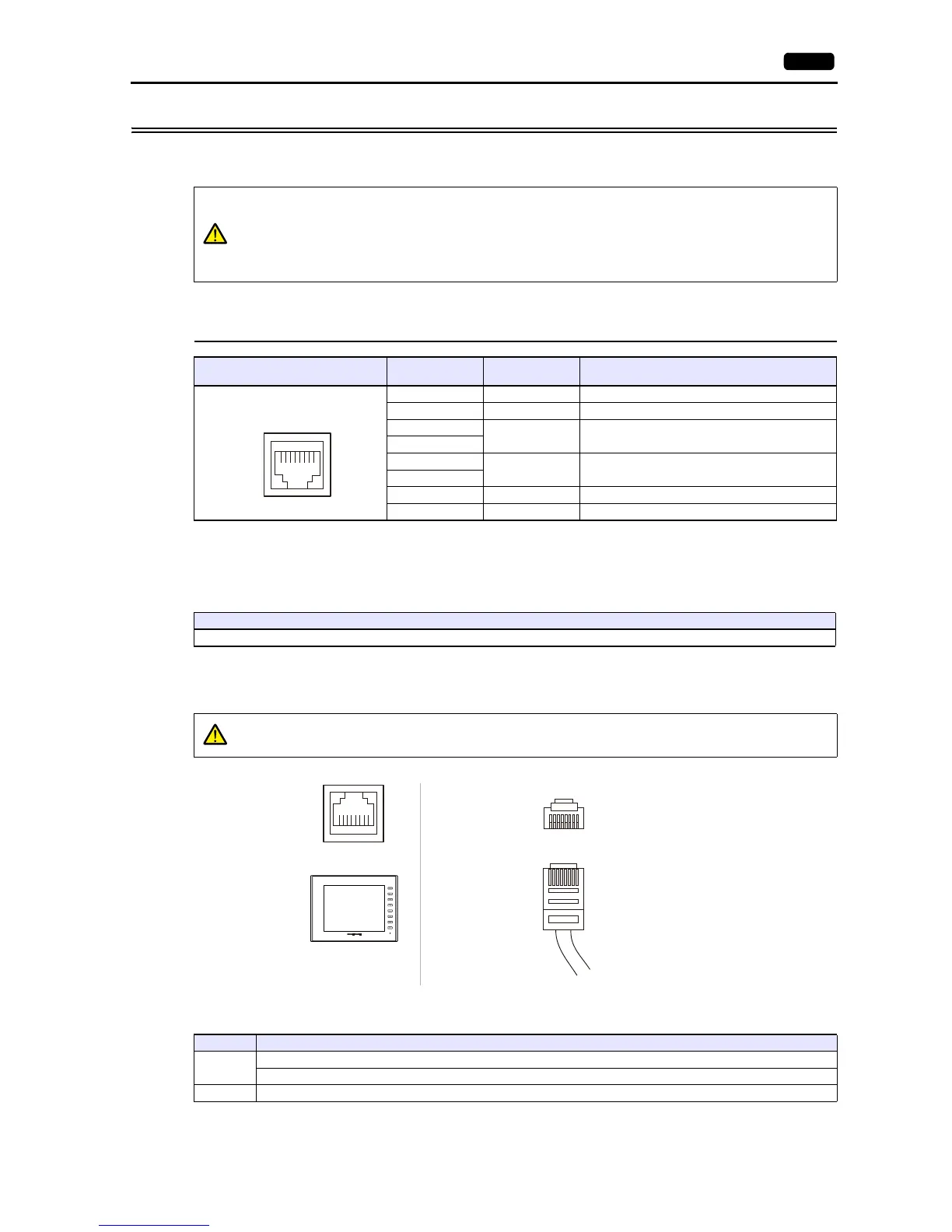
MJ1/MJ2
* For MJ1, MJ2 and USBA, the maximum allowable current is 150 mA in total (only when the installation angle of MONITOUCH is within 60
to 120).
Recommended Cable
Notes on Configuring a Cable
Applicable Devices
MJ1 and MJ2 use the same type RJ-45 connector as the LAN connector.
To prevent damage to the device from an external power supply of the MJ, check the indication
on the unit and insert a cable in the correct position.
MJ1 and MJ2 are not usable for connection via RS-422 (4-wire system). Use the CN1 port
instead or a commercially available RS-232C-to-RS-422 converter.
MJ1/MJ2
RJ-45 8pin
No. Signal Contents
1 +SD/RD RS-485 + data
2 SD/RD RS-485 data
3
+5V
Externally supplied +5 V
*
4
5
SG Signal ground
6
7 RD RS-232C receive data
8 SD RS-232C send data
12345678
Recommended Cable
Hakko Electronics’ cable “V6-TMP” 3, 5, 10 m
Pins No. 3 and 4 are provided for external power supply. To prevent damage to the device due to
wrong connection, check the pin numbers and connect wires correctly.
Pin arrangement
on the cable
Pin arrangement
on MONITOUCH
Port Applicable Devices
MJ1
Computer (screen program transfer)
PLC, temperature controller, inverter, servo, barcode reader, V-Link, slave communication (Modbus RTU), serial printer
MJ2 PLC, temperature controller, inverter, servo, barcode reader, V-Link, slave communication (Modbus RTU), serial printer