16.2 Temperature Controller/Servo/Inverter Connection 16-31
16.2.6 F-MPC04P (Loader)
Communication Setting
Editor
Communication setting
(Underlined setting: default)
*1 To use port No. 32 to 99, use the station number table.
Power Monitor Unit
Be sure to match the settings to those made under [Communication Setting] of the editor.
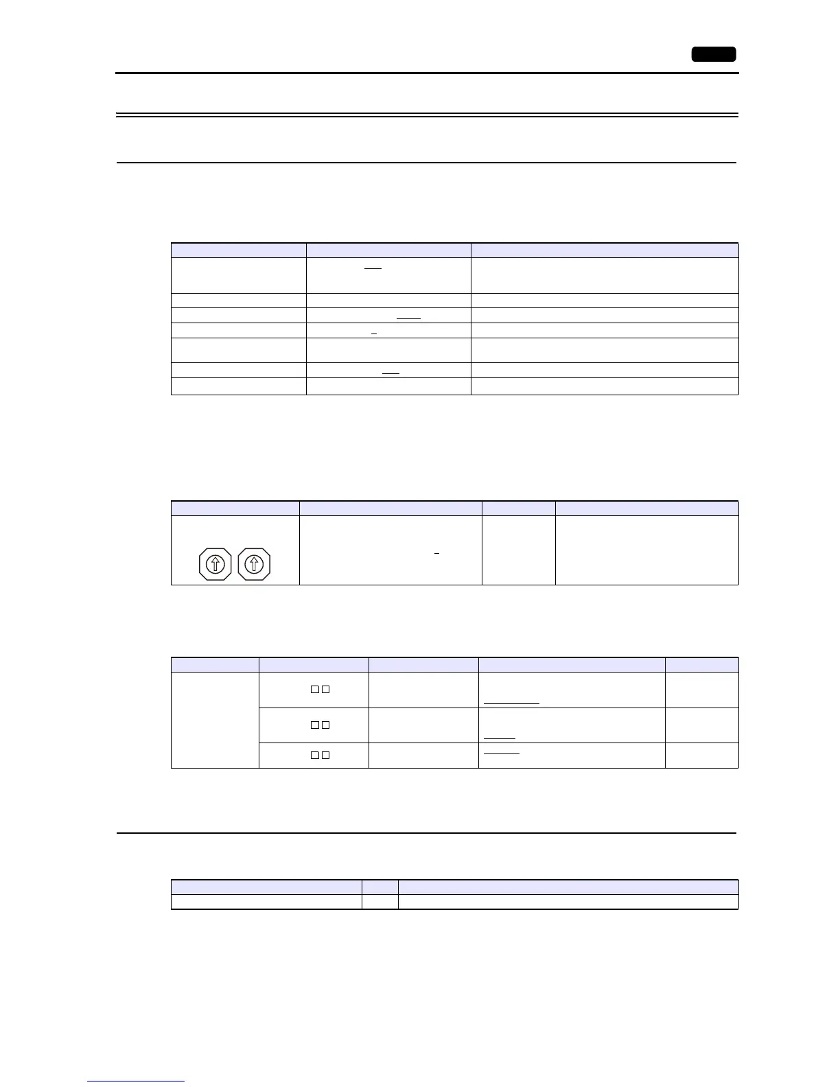
Station number setting
Communication setting
The communication parameter can be set using keys attached to the front of the power monitor unit.
(Underlined setting: default)
* The communication parameter (stop bit) is fixed to 1 bit.
Available Device Memory
The available setting range of device memory varies depending on the model. Be sure to set within the range available for the
model to be used. Use [TYPE] when assigning indirect device memory for macro programs.
Item Setting Remarks
Connection Mode
1:1 / 1:n
/ Multi-link2 /
Multi-link2 (Ethernet) /
1:n Multi-link2 (Ethernet)
Signal Level RS-422/485
Baud Rate 4800 / 9600 / 19200
bps
Data Length 7
/ 8 bits
Stop Bit 1 bit
Do not change the default setting because the setting on the
power monitor unit cannot be changed.
Parity None / Odd
/ Even
Targe t Por t N o.
1 to 99
*1
Station Setting Example Remarks
01 to 99 [DEC] (default: 0
)1
Circuit No. Setting Code Item Setting Example
C
L1-
Baud rate
00: 4800 bps
01: 9600 bps
02: 19200 bps
02
L2-
Parity
00: None
01: Even
02: Odd
02
L3-
Data length
00: 7 bits
01: 8 bits
00
ADDRESS SW
0
1
2
3
4
5
6
7
8
9
0
1
2
3
4
5
6
7
8
9
Device Memory TYPE Remarks
--- 00H Double-word