16-16 16. Fuji Electric
PLC Table
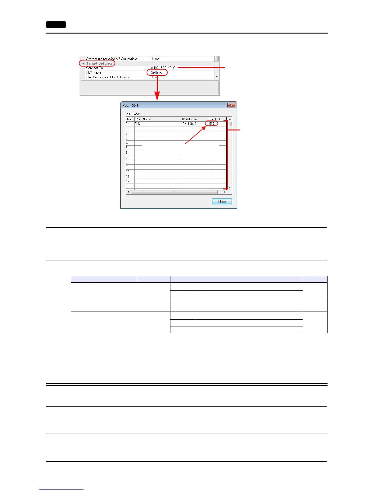
[System Setting] [Hardware Setting] [PLC Properties] [Target Settings] [PLC Table]
Available Device Memory
The available device memory is the same as the one described in “16.1.4 MICREX-SX SPH/SPB Series (IEC Mode)”.
PLC_CTL
Macro command “PLC_CTL F0 F1 F2”
*1 Valid only when “1:n” connection mode is selected under [Communication Setting] in the [PLC Properties] window ([System Setting]
[Hardware Setting]).
For the station number, set the PLC table number under [Target Settings] in the [PLC Properties] window ([System Setting] [Hardware
Setting]).
*2 Valid only for a redundant system.
16.1.9 MICREX-SX (Ethernet) (N Mode / F Mode)
Communication Setting
The communication setting is the same as the one described in “16.1.8 MICREX-SX (Ethernet) (IEC Mode)”.
Available Device Memory
The available device memory is the same as the one described in “16.1.5 MICREX-SX SPH/SPB Series (N Mode / F Mode)”.
PLC_CTL
The macro command is the same as the one described in “16.1.8 MICREX-SX (Ethernet) (IEC Mode)”.
When the self port standard number set on
the PLC is “256”, specify “507” (256 + 251).
Valid only for 1 : 1 connection
Select the PLC for connection from those
registered on the PLC table.
Set the IP address, port number 507 and
whether or not to use the KeepAlive
function of the PLC.
Contents F0 F1 (= $u n) F2
All start
1 - 8
(PLC1 - 8)
n
Station number: 00H to FFH
*1
2
n + 1 Command: 0400H
All stop
1 - 8
(PLC1 - 8)
n
Station number: 00H to FFH
*1
2
n + 1 Command: 0402H
Operation / standby switching
*2
1 - 8
(PLC1 - 8)
n
Station number: 00H to FFH
*1
3
n + 1 Command: 040BH
n + 2 CPU No. operated by default: m (0, 2, 4, 6)