EasyManuals Logo

Hakko Electronics Monitouch V9 Series User Manual

Hakko Electronics Monitouch V9 Series
430 pages
To Next Page IconTo Next Page
To Previous Page IconTo Previous Page
Page #138 background imageLoading...
Page #138 background image
4.2 Temperature Controller/Servo/Inverter Connection 4-7
Instrumentation Network Module
Ethernet Connection
Instrumentation Network Module
*1 For KeepAlive functions, see “1.3.2 Ethernet Communication”.
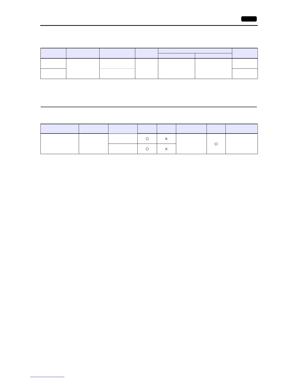
PLC Selection
on the Editor
CPU Unit/Port Signal Level
Connection
Lst File
CN1 MJ1/MJ2
NX (CPL)
NX-D15
NX-D25
NX-D35
Built-in terminal
RS-485 Wiring diagram 1 - C4 Wiring diagram 1 - M4
NX_CPL.Lst
NX (MODBUS
RTU)
NX-CB1N (terminal)
NX-CB1R (terminal)
NX_Mod.Lst
PLC Selection on the
Editor
CPU Unit/Port TCP/IP UDP/IP Port No.
Keep
Alive
*1
Lst File
NX (MODBUS TCP/IP)
NX-D15
NX-D25
NX-D35
NX-CB1N
NX-CB1R
502: Default
(Max. 2 units)
NX_Mod_Eth.Lst
NX-CR1

Table of Contents

Other manuals for Hakko Electronics Monitouch V9 Series

Questions and Answers:

Question and Answer IconNeed help?

Do you have a question about the Hakko Electronics Monitouch V9 Series and is the answer not in the manual?

Hakko Electronics Monitouch V9 Series Specifications

General IconGeneral
BrandHakko Electronics
ModelMonitouch V9 Series
CategoryMonitor
LanguageEnglish

Related product manuals