16.2 Temperature Controller/Servo/Inverter Connection 16-75
16.2.26PHR (MODBUS RTU)
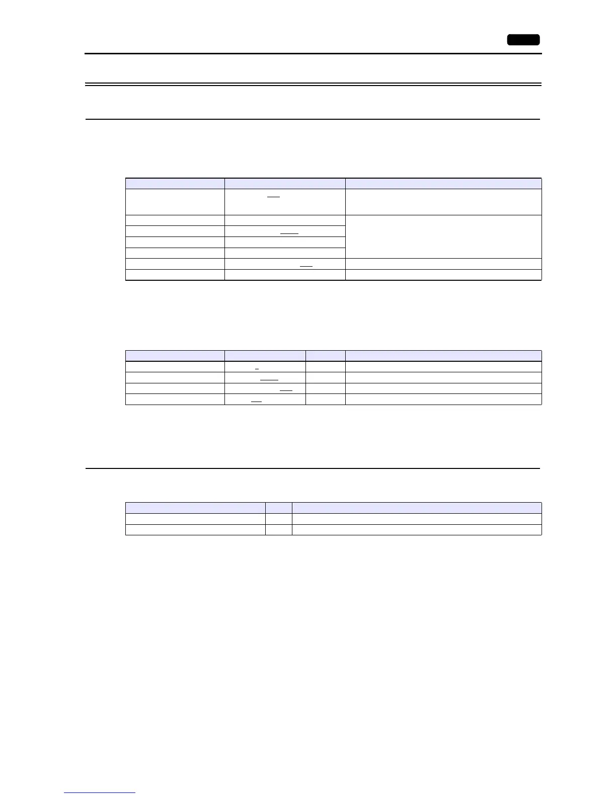
Communication Setting
Editor
Communication setting
(Underlined setting: default)
Recorder
The communication parameters can be set using keys attached to the front of the recorder.
Be sure to match the settings to those made under [Communication Setting] of the editor.
(Underlined setting: default)
*1 The communication function of the recorder can be selected at the time of purchase. Select a model on which RS-485 communication is
available.
*2 The following communication parameters are fixed; data length: 8 bits and stop bit: 1 bit.
Available Device Memory
The available setting range of device memory varies depending on the model. Be sure to set within the range available for the
model to be used. Use [TYPE] when assigning indirect device memory for macro programs.
Item Setting Remarks
Connection Mode
1:1 / 1:n
/ Multi-link2 /
Multi-link2 (Ethernet) /
1:n Multi-link2 (Ethernet)
Signal Level RS-422/485
Do not change the default settings of the signal level, data
length and stop bit because these settings on the recorder
cannot be changed.
Baud Rate 9600 / 19200
bps
Data Length 8 bits
Stop Bit 1 bit
Parity None / Even / Odd
Target Port No. 1 to 31
Parameter Setting Example Remarks
Modbus station No. 1
to 31 1
Modbus baud rate 9600 / 19200
bps 19200 bps
Modbus parity None / Even / Odd
Odd
Front communication function ON
/ OFF ON Be sure to set to “ON”.
Device Memory TYPE Remarks
4 (holding register) 02H
3(input register) 03H