16-12 16. Fuji Electric
Indirect Device Memory Designation
Specify the CPU number in the expansion code.
PLC_CTL
Macro command “PLC_CTL F0 F1 F2”
*Valid only for the redundant system.
16.1.5 MICREX-SX SPH/SPB Series (N Mode / F Mode)
Communication Setting
The communication setting is the same as the one described in “16.1.4 MICREX-SX SPH/SPB Series (IEC Mode)”.
Available Device Memory
The available setting range of device memory varies depending on the PLC model. Be sure to set within the range available for
the PLC to be used. Use [TYPE] when assigning indirect device memory for macro programs.
*1 Input/output memory does not operate normally unless you import the “*.ini” file created using [Export Device Information] in the PLC
programming tool.
Can be used only for PLC1. Indirect designation is not available.
*2 Double-word addresses (DM, DL, DSM) can be specified only for PLC1.
In the case with PLC2 to PLC8, access to the above addresses is possible when the data length is set to 2 words in the word address (WM,
WL, WSM).
Example: When accessing the address in DM100:
Set the data length to 2 words for WM100.
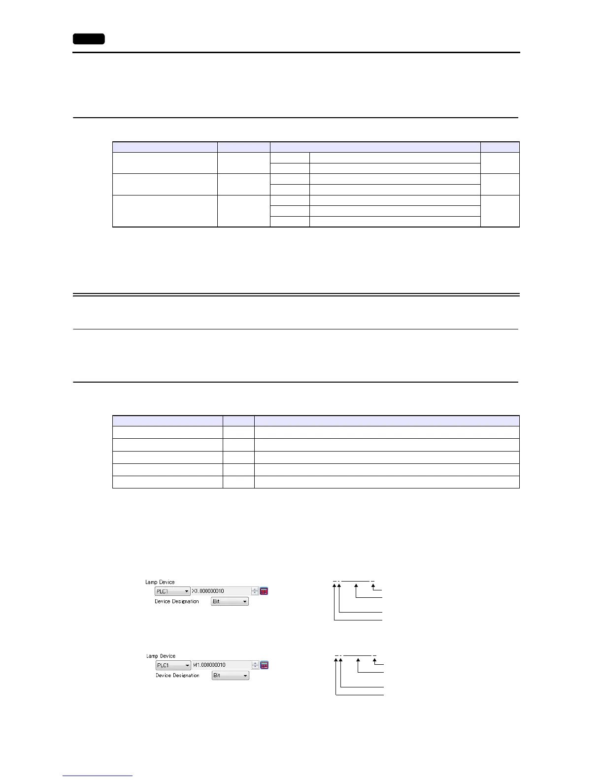
*3 The assigned device memory is expressed as shown below when editing the screen.
- For X or Y:
- For M, L or SM
Indirect Device Memory Designation
Specify the CPU number in the expansion code.
Contents F0 F1 (= $u n) F2
All start
1 - 8
(PLC1 - 8)
n Station number: 0000H
2
n + 1 Command: 0400H
All stop
1 - 8
(PLC1 - 8)
n Station number: 0000H
2
n + 1 Command: 0402H
Operation / standby switching
*
1 - 8
(PLC1 - 8)
n Station number: 0000H
3n + 1 Command: 040BH
n + 2 CPU No. operated by default: m (0, 2, 4, 6)
Device Memory TYPE Remarks
X (input memory)
*1
-
WX as word device, DX as double-word device
*3
Y(output memory)
*1
-
WY as word device, DY as double-word device
*3
M (standard memory) 02H
WM as word device, DM as double-word device
*2 *3
L(retain memory) 04H
WL as word device, DL as double-word device
*2 *3
SM (system memory) 08H
WSM as word device, DSM as double-word device
*2 *3