16.2 Temperature Controller/Servo/Inverter Connection 16-69
16.2.23FALDIC- Series
Communication Setting
Editor
Communication setting
(Underlined setting: default)
Servo Amplifier
Set the communication parameters using the touch panel mounted on the servo amplifier.
Be sure to match the settings to those made under [Communication Setting] of the editor.
(Underlined setting: default)
*1 The communication function of the servo amplifier can be selected at the time of purchase. Select a model on which host interface:
universal communication (RS-485) is available.
*2 The following communication parameters are fixed; data length: 8 bits, stop bit: 1 bit, and parity: even.
Available Device Memory
The available setting range of device memory varies depending on the model. Be sure to set within the range available for the
model to be used. Use [TYPE] when assigning indirect device memory for macro programs.
*1 Input a parameter number by manual operation.
*2 Address denotations XXYY
Item Setting Remarks
Connection Mode
1:1 / 1:n
/ Multi-link2 /
Multi-link2 (Ethernet) /
1:n Multi-link2 (Ethernet)
Signal Level RS-422/485
Do not change the default setting other than baud rate because
the setting on the servo amplifier cannot be changed.
Baud Rate 9600
/ 19200 / 38400 bps
Data Length 8 bits
Stop Bit 1 bit
Parity Even
Target Port No. 1 to 31
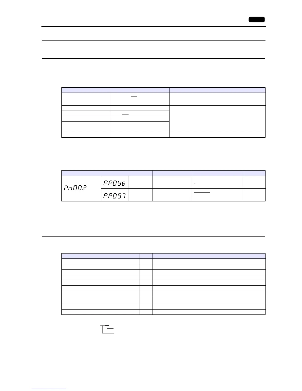
Parameter Item Setting Example
System parameter
(No. 96) Station number 1
to 31 1
(No. 97) Baud rate
0: 9600 bps
1: 19200 bps
2: 38400 bps
0
Device Memory TYPE Remarks
00 (monitor data) 00H Double-word, read only
01 (data on positioning being executed) 01H Double-word, read only
10 (sequence mode) 02H Read only
11 (control input/output signal) 03H Read only
12 (alarm detection log) 04H Read only
13 (detected alarm contents) 05H Read only
20 (standard parameter) 06H
Double-word
*1
21 (system parameter) 07H
Double-word
*1
30 (positioning data) 08H
Double-word
*2
40 (control command) 09H Double-word, write only