16.2 Temperature Controller/Servo/Inverter Connection 16-49
16.2.12FRENIC5000 G11S / P11S (MODBUS RTU)
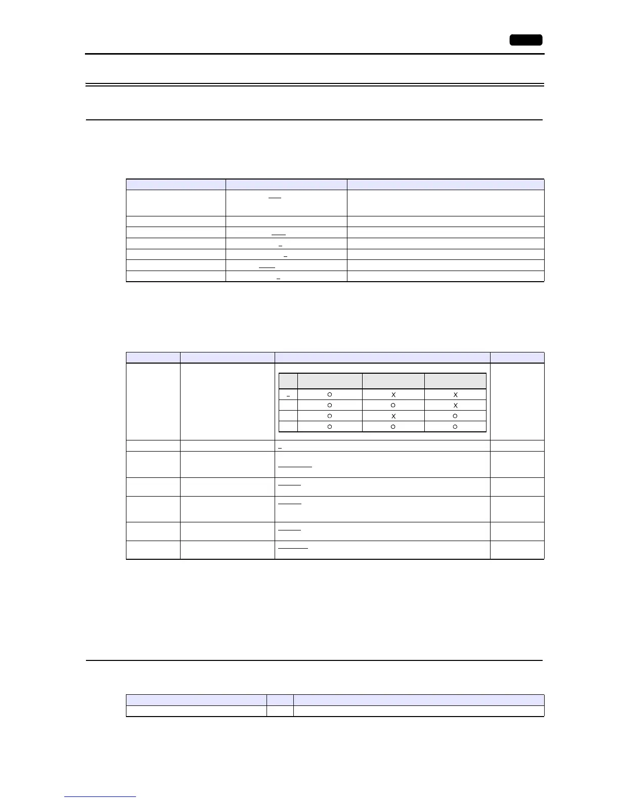
Communication Setting
Editor
Communication setting
(Underlined setting: default)
Inverter
Set communication parameters.
Be sure to match the settings to those made under [Communication Setting] of the editor.
(Underlined setting: default)
*1 Available when the communication is enabled by digital input.
Example: To make the communication enabled when digital input terminal X1 is turned ON;
Set “24 (link operation)” for function code E01 and turn on the digital input terminal X1 externally.
Terminals from X2 to X9 can also be used. Set the function code corresponding to the digital input terminal to use.
*2 When “FRENIC5000G11S/P11S (MODBUS RTU)” is selected for model selection on the editor, select “Modbus RTU” for the
communication protocol on the inverter.
Available Device Memory
The available setting range of device memory varies depending on the model. Be sure to set within the range available for the
model to be used. Use [TYPE] when assigning indirect device memory for macro programs.
Item Setting Remarks
Connection Mode
1:1 / 1:n
/ Multi-link2 /
Multi-link2 (Ethernet) /
1:n Multi-link2 (Ethernet)
Signal Level RS-422/485
Baud Rate 4800 / 9600
/ 19200 bps
Data Length 8
bits
Stop Bit 1 / 2
bits
Parity None
/ Odd / Even
Targe t Por t N o. 1
to 31
Function Code Item Setting Example
H30
Link function
*1
3
H31 Station address 1
to 31 1
H34 Baud rate
0: 19200 bps
1: 9600 bps
2: 4800 bps
1
H35 Data length
0: 8 bits
1: 7 bits
0
H36 Parity bit
0: None
1: Even
2: Odd
0
H37 Stop bit
0: 2 bits
1: 1 bit
0
U49
Communication protocol
*2
0: FGI-bus
1: Modbus RTU
1