15.1 PLC Connection 15-3
Available Device Memory
The available setting range of device memory varies depending on the PLC model. Be sure to set within the range available for
the PLC to be used. Use [TYPE] when assigning indirect device memory for macro programs.
*1 When using consecutive bit devices, select device memory “D” for improved performance.
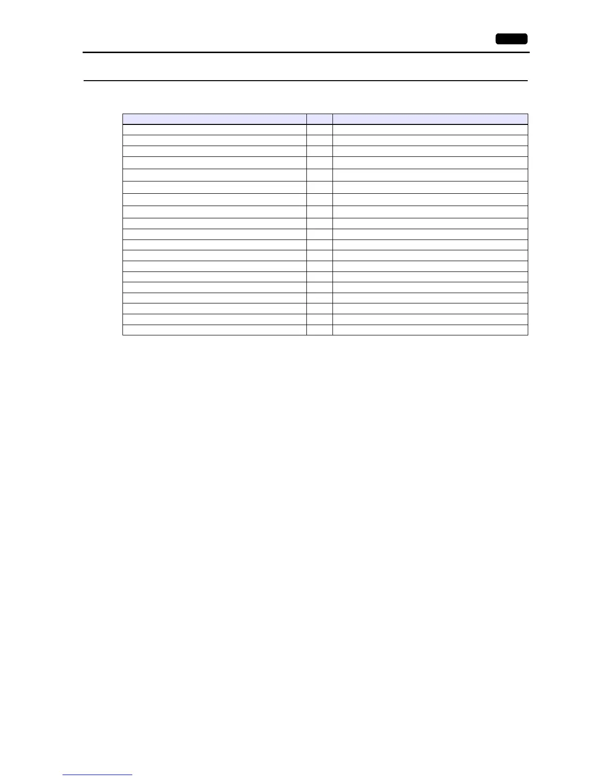
Device Memory TYPE Remarks
D (Data area) 00H
T (Timer relay area) 01H Read only
C (Counter relay area) 02H Read only
R (Accessory relay area) 03H
Common to D0 to D15
*1
X (Input channel) 04H
Common to D16 to D30
*1
Y (Output channel) 05H
Common to D31 to D40
*1
S (System relay area) 06H
Common to D41 to D55
*1
K (Thermal control relay area) 07H
Common to D56 to D63
*1
TSW (Timer setting area) 08H Common to D208 to D335
TP (Present timer setting area) 09H Read only, common to D336 to D463
CSW (Counter setting area) 0AH Common to D464 to D591
CP (Present counter setting area) 0BH Read only, common to D592 to D719
KJS (Thermal control temperature setting) 0CH Common to D80 to D95
KP (Present thermal control temperature setting) 0DH Read only, common to D96 to D111
KJL (Thermal control low-temperature alarm setting) 0EH Common to D112 to D127
KJH (Thermal control high-temperature alarm setting) 0FH Common to D128 to D143
KI (Present thermal control current setting) 10H Read only, common to D144 to D159
KJC (Insufficient thermal control) 11H Common to D160 to D175
KJR (Thermal control cycle setting) 12H Common to D192 to D207