16.2 Temperature Controller/Servo/Inverter Connection 16-51
When Connecting to the Terminal Block on “OPC-VG7-RS” (Optional Communication Board):
Communication setting
Set communication parameters.
Be sure to match the settings to those made under [Communication Setting] of the editor.
(Underlined setting: default)
*1 Available when the communication is enabled by digital input.
Example: To make the communication enabled when digital input terminal X1 is turned ON;
Set “24 (link operation)” for function code E01 and turn on the digital input terminal X1 externally.
Terminals from X2 to X9 can also be used. Set the function code corresponding to the digital input terminal to use.
*2 When “FRENIC5000G11S/P11S (MODBUS RTU)” is selected for model selection on the editor, select “Modbus RTU” for the
communication protocol on the inverter.
*3 The communication parameter (data length) is fixed to 8 bits.
Available Device Memory
The available setting range of device memory varies depending on the model. Be sure to set within the range available for the
model to be used. Use [TYPE] when assigning indirect device memory for macro programs.
Function Code Item Setting Example
H30
Link function
*1
3
H31 Station address 1
to 31 1
o37
Communication definition
setting
10
H40
Communication protocol
*2
0: FGI-bus
1: SX (loader) protocol
2: Modbus RTU
2
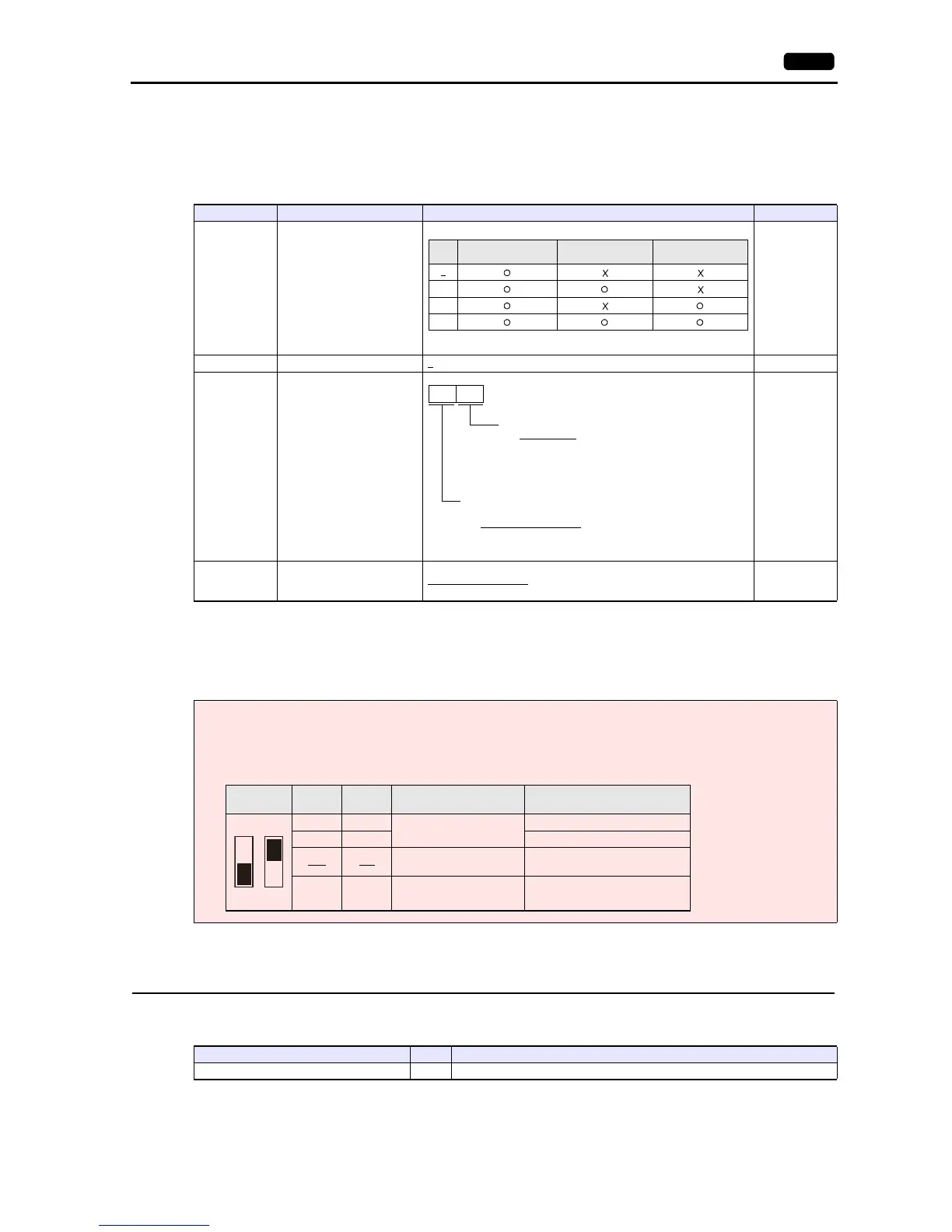
Notes on Using “OPC-VG7-RS” (Optional Communication Board)
Set the DIPSW2 on the optional communication board “OPC-VG7-RS” as shown below when connecting the V9 and the
terminal block of the board.
Baud rate
0: 38400 bps
1: 19200 bps
2: 9600 bps
3: 4800 bps
Parity
0: None (stop bit: 2 bits)
1: Even (stop bit: 1 bit)
2: Even (stop bit: 1 bit)
The underlined settings are set as default.
SW2
SW2-1
Setting
SW2-2
Setting
Function Remarks
OFF OFF
-
-
ON OFF -
OFF
ON
Optional communication
board enabled
Do not change the default setting
when connecting with the V9.
ON ON - -