Chapter 6 Remote Management using EMS Refreshing the EMS Screen
© 2012 Harmonic Inc. 73 ProView 7000 v.2.6, Rev. E
The Device Explorer tab displays a hierarchy-map of the input and output ports, transport-
streams, programs, elementary streams, PIDs, Tables, CAMs and decoders that are currently
connected and cross-connected by the ProView 7000™ selected for management on the
EMS.
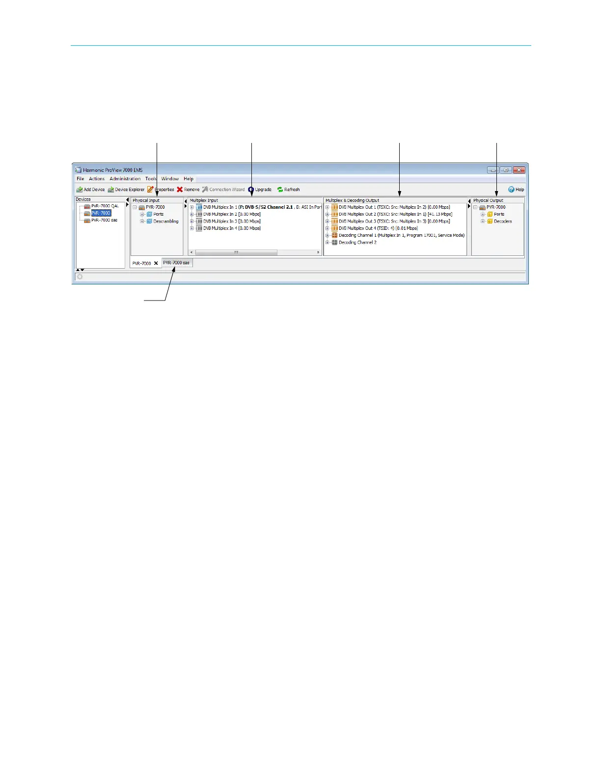
Figure 6–3: Device Explorer tab
■ The Device Explorer tab is divided into four boxes, see Figure 6–3. It comprises:
❑ Physical Input ports box, deals with the features of the device input physical interfaces
(see 7.1 Physical Input Ports and Slots).
❑ Multiplex Input box, deals with the multiplexing features of the input stream (see
7.2 Multiplex Inputs).
❑ Multiplex & Decoding Output box, deals with the multiplexing and decoding features of
the output stream (see 7.3 Multiplex & Decoding Outputs).
❑ Physical Output ports box, dealing with the features of the device output physical
interfaces (see 7.4 Physical Outputs).
The ProView 7000™ EMS GUI uses a wide range of icons to identify elements displayed on the
Device Explorer tab, see Appendix C, Device Explorer Icons.
Physical Input Multiplex Input Physical OutputMultiplex & Decoding Output
Device Explorer tab