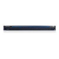
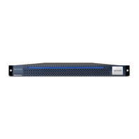
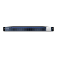
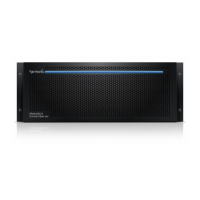
MediaPort 7000 Series module rear panel
Key Component Description
7 LTC IN Channel A
8 LTC OUT Channel B
9 LTC IN Channel B
10 LTC OUT Channel B
Use these connectors for an analog LTC
(longitudinal timecode) signal: two input (IN)
and two output (OUT). When LTC is present at
the IN port and a Player has been configured
to record LTC, LTC timecode will be embedded
in the DV stream. On playback, timecode can
be routed from the OUT port to an external
device such as a timecode reader/character
generator for inserting code in frame.
Note that some devices (such as Sony*
Betacam* decks) will not display LTC timecode
unless the source timecode is changing. For
example, if the clip is in “cue play” or “play
zero-speed” mode, the timecode shown on the
Sony deck may be incorrect.
11, 12 Reference Loop Use these connectors to connect reference
black video to the MediaPort. Reference
black video should be looped through these
connectors and then eventually terminated.
13 Soft Power The Soft Power button is a momentary switch
that is used to perform a “soft” reset of the
MediaPort. Once pressed, all boards reset and
code is re-loaded. The function is similar to
clicking the Reboot button on the MediaPort
Properties page in SystemManager.
14 Status/Wink LED The Status/Wink LEDdisplays blue to indicate
power is ON. The LED will blink (wink) when
its wink mode is activated.
15 GPIO Connector The GPIO connector can be used for player
and Playout Control.
16 RS-422 Port Use this connector (RJ-45) for RS-422 serial
control. The LEDs represent connection status.
17 Ethernet Port Not applicable for systems running 8.4 and
later software; only systems running 8.3.x.x
and earlier software use this port.
18 Ethernet Port Use this Ethernet port to connect to the
Spectrum video server. Note that the Activity
LED on the left side of the port blinks when
data is being sent or received.
Related information
About MediaPort 7000 and ChannelPort timing on page 156
MediaPort 7000 GPIO signal assignments on page 156
Serial control connections for a MediaPort 7000 and a ChannelPort on page 156
155 Spectrum System 8.4 Installation Guide