Chapter 8: ChannelPort module hardware reference
For information on configuring GPIO triggers using SystemManager, refer to “Configuring ChannelPort
GPIO triggers” in the Harmonic SystemManager User Guide.
For information on configuring the serial connections for use with automation or an EAS, see "Configuring
a Spectrum X or ChannelPort Channel" in the Harmonic SystemManager User Guide.
Serial control connections for a MediaPort 7000 and a
ChannelPort
The MediaPort 7000 and the ChannelPort modules include an RJ-45 port for RS-422 serial control
connections with an automation system.
NOTE: Because manufacturer specifications for cables, connectors and adapters
can change, always consult with your control system vendor first for the most current
information on interface equipment and peripherals.
NOTE: Depending on the MediaPort, there can be between one and six serial control
ports, each of which controls an independent DVB/ASI output. You are not required to use
all available ports.
On both the MediaPort 7000 and the ChannelPort, the left-most RJ-45 connector is wired for two
channels (Ch 0 and Ch 1). Harmonic supplies an RJ-45/ DB-9 splitter cable, which provides the Channel
0 on one DB-9 and the Channel 1 signals on the other.
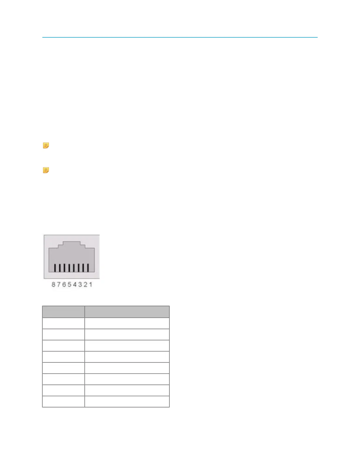
Pinout assignments for the RS-422 port on the MediaPort 7000 and the ChannelPort modules is shown in
the following diagram. The connector type is RJ-45 (female)
Figure 8-6: MediaPort 7000/ChannelPort RS-422 Port Pinout
Pin Signal
1 RX+ (Ch 0)
2 RX- (Ch 0)
3 TX+ (Ch 0)
4 RX+ (Ch 1)
5 RX- (Ch 1)
6 TX- (Ch 0)
7 TX+ (Ch 1)
8 RX- (Ch 1)
182