Chapter 1: Introduction
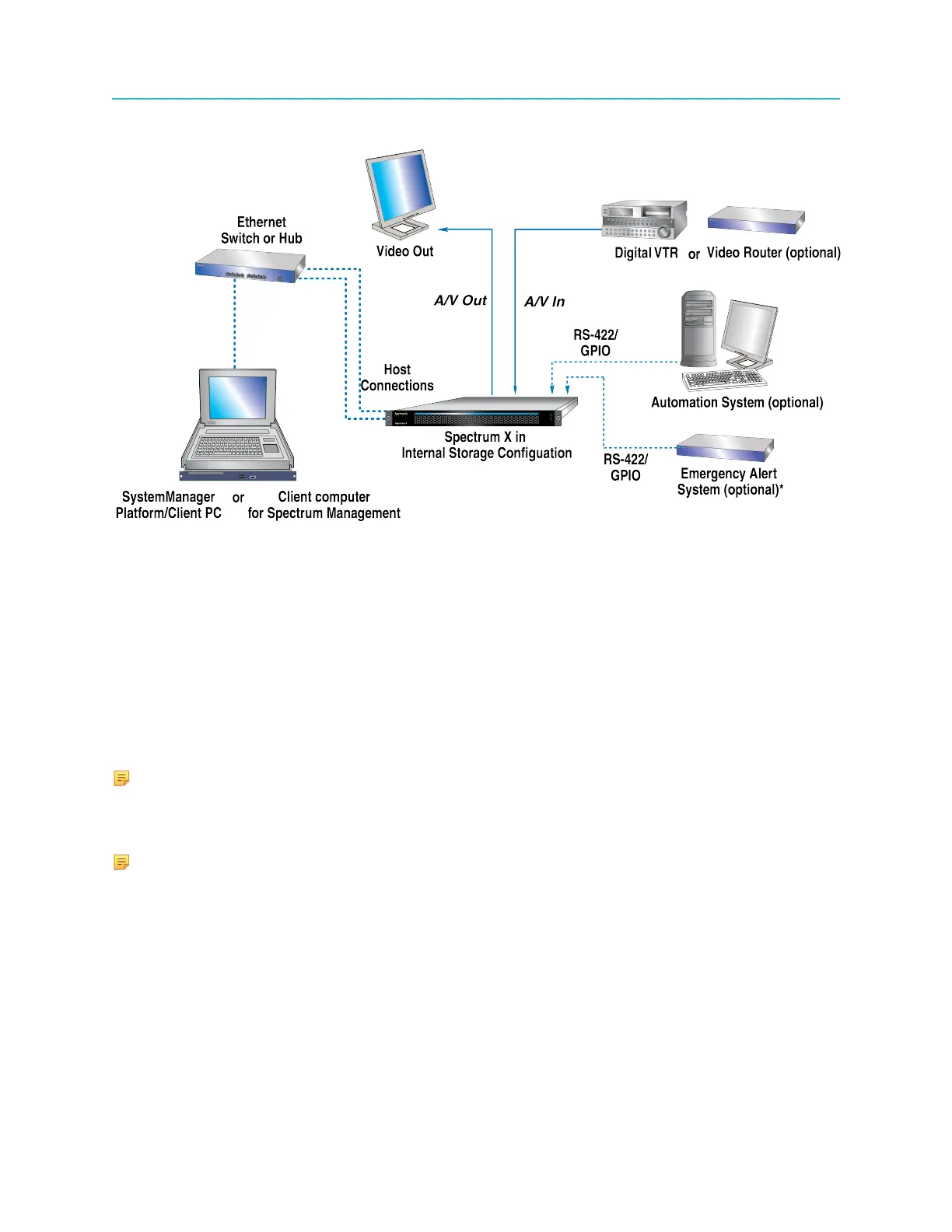
The following figure illustrates a Spectrum system layout with one Spectrum X.
Figure 1-3: Spectrum X system layout
Note that, in this sample system diagram, the following are not supplied by Harmonic:
• Digital VTR (If an Analog VTR is used, external A-D converters are required.)
• Video Monitors
• RS-422 interconnection cables (DB-9 Male to DB-9 Male)
• Audio/Video interconnection cables and monitoring equipment
• Gigabit Ethernet switch
• (Optional) Automation System
• (Optional) Emergency Alert System
• (Optional) Video router
NOTE: An Ethernet switch is required if your Harmonic system includes applications
(such as archiving and editing) that would be optimized by Gigabit Ethernet connectivity.
In systems that do not include these types of applications (such as the automation system
described above) an Ethernet hub is sufficient.
NOTE: For all coaxial cable requirements, always use 75-ohm cable that is specifically
designed for digital video, and which meets the precise transport standards for SD video at
270 Mbps and HD video at 3.0 Gbps.
Spectrum X installation overview (internal storage configuration)
Make sure to install and cable your Spectrum X system in the order provided.
1. Rack mount the system. See Rack mounting instructions on page 19.
2. Install the bezel. See Installing the Spectrum X bezel on page 35.
3. Connect to SystemManager. See Connecting to the SystemManager on page 55.
4. Connect to a client system for file transfers. See Connecting to a client system or a Harmonic
MediaGrid for file transfers on page 60.
16