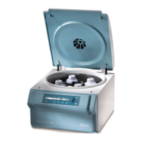
Fig. 15: Front wooden beam
1 Fastening screws
2 Front wooden beam
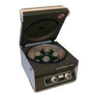
Fig. 16: Fastening metal rails
1 Metal rails
2 Nails
3 Wooden pallet
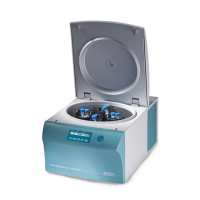
Fig. 17: Wooden beam under the metal
rails
1 Metal rails
2 Front wooden beam
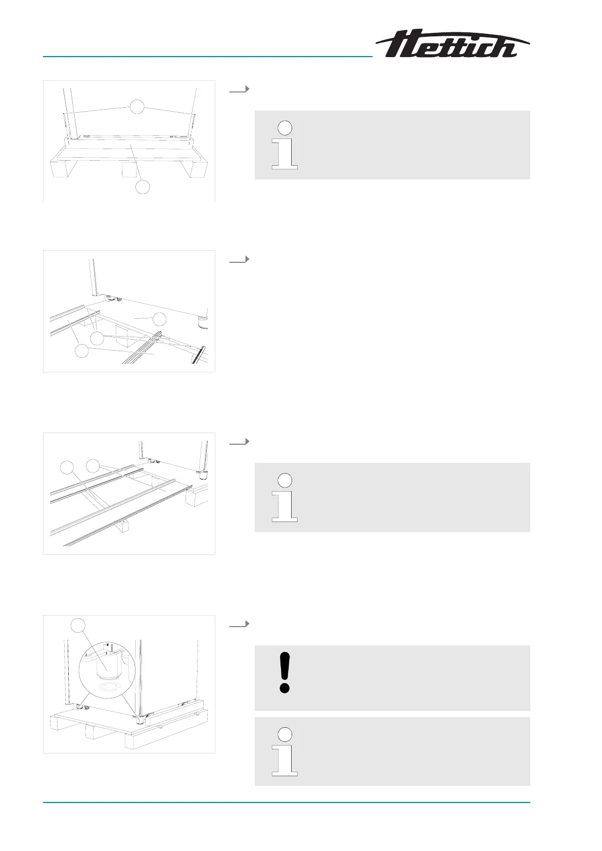
Fig. 18: Screwing in levelling elements
1 Device feet
1. Remove the two fastening screws and remove the front
wooden beam.
In the case of devices with the optional glass
door, there are additional reinforcements
attached to the wooden beam. These can be
removed with the beam.
2. Fasten the two metal rails to the wooden pallet with two nails
each.
3. Push the front wooden beam under the metal rails to support
these.
The angle between the metal rails and the oor
must not be more than 6°.
4. Screw the front levelling elements completely into the device
feet (upwar
d).
NOTICE
The levelling elements have a height of 60 mm
when scr
ewed-in. Hereby, the inner part proj-
ects 3 mm with respect to the outer part.
The rear levelling elements are already screwed
in ex works.