Fig. 151: ‘Tolerance band’ menu
6.13.4 Tolerance band
In this menu, you can make the settings for the toler-
ance band alarm.
-5 K
+3 K
+ 3 K
- 5 K
B
A
D
C
C
C
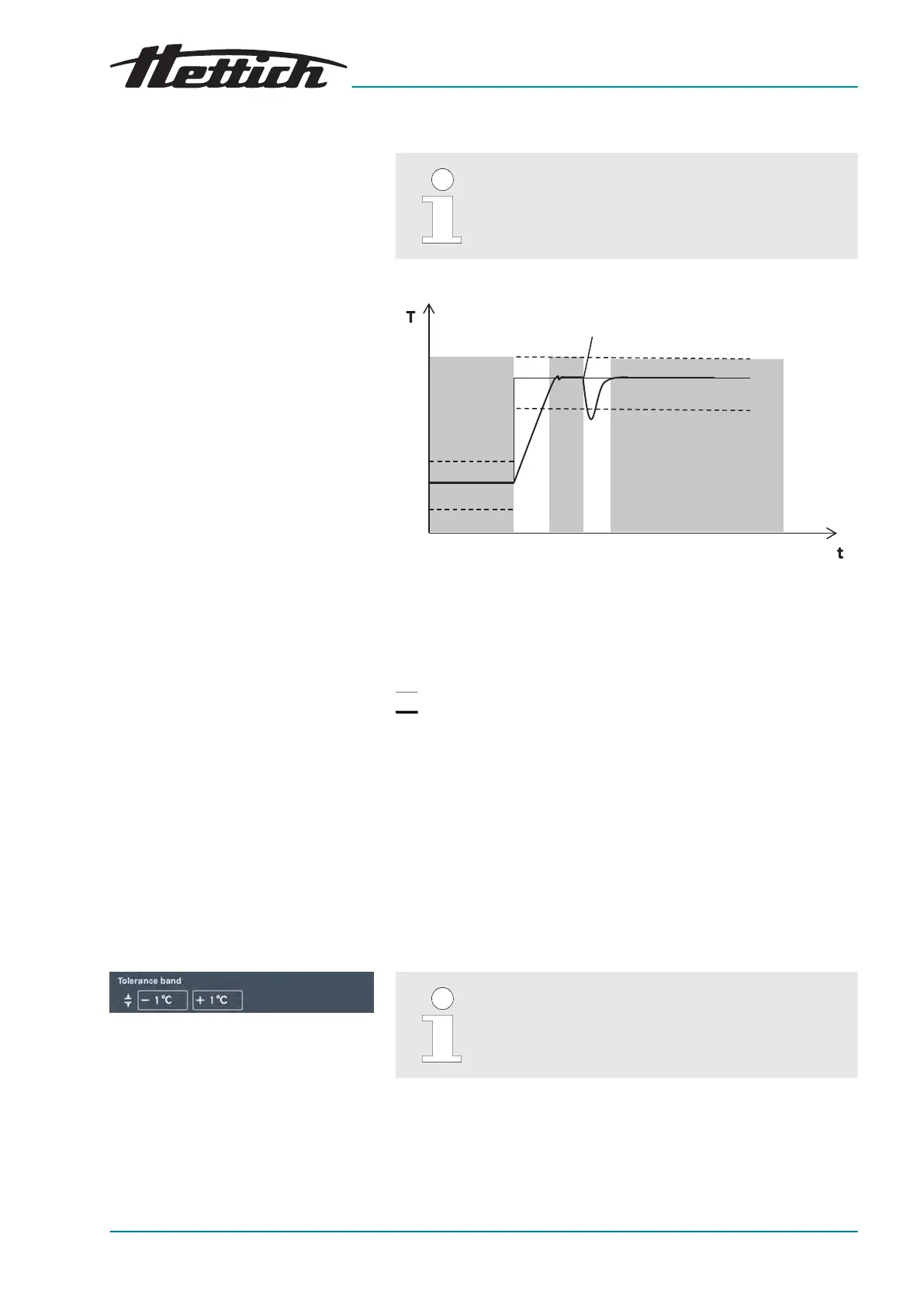
Fig. 150: Tolerance band.
A Temperature 2
B Temperature 1
C Alarm active (grey background on the diagram)
D Door opening
- - - Temperature limit
Temperature setpoint
Actual temperature value
The tolerance band is the result of setting the upper and lower tem-
peratur
e limits. It is monitored whether the ACTUAL temperature is
within the tolerance band.
The tolerance band limits can be set symmetrically or asymmetrically
around the temperature setpoint. Ex works, these are set to ±1 °C or
± 2 °F.
The tolerance band limits can be dened in steps of 1 °C or 1 °F
between 1 °C and 30 °C or 2 °F and 54 °F.
If the actual temperature goes beyond one of the tolerance band
limits, an optical and acoustical alarm will be output. The potential-
free alarm output is switched.
Violations of the tolerance band are logged and can
be viewed and evaluated at any time.
Example of an asymmetrical tolerance band setting:
■ The current temperature setpoint is set to 37 °C.
■ The upper tolerance band limit is set to +3 °C.
■ The lower tolerance band limit is set to -5 °C.