47
Conguring CAN Settings
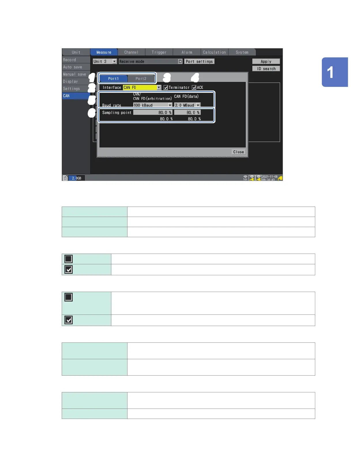
Conguring port settings
1
2
3
4
5
6
1
Select the CAN Unit’s port.
2
Select the interface.
CAN CAN mode
CAN FD
CAN FD mode (ISO 11898-1:2015 compliant)
CAN FD(non-ISO) CAN FD (non-ISO) mode (not ISO compliant)
3
Select the [Terminator] check box.
Places CAN_H and CAN_L in an open state.
Inserts a 120
Ω
terminal resistance between CAN_H and CAN_L.
4
Select the [ACK] check box.
Does not send ACK frames from the CAN controller.
The instrument will not be able to send user frames or operate in measured value
output mode.
Sends ACK frames from the CAN controller.
5
Under [Baud rate], select the CAN communications speed.
CAN/
CAN FD (arbitration)
CAN/CAN FD arbitration phase communications rate
50 k, 62.5 k, 83. 3 k, 100 k, 125 k, 250 k, 500 k
, 800 k, 1000 k [Baud]
CAN FD (data) CAN FD data phase communications rate
0.5 M, 1.0 M, 2.0 M
, 2.5 M, 4.0 M, 5.0 M [Baud]
6
Under [Sampling point], set the display sampling point.
CAN/
CAN FD (arbitration)
50.0% to 95.0%, 80.0%
CAN FD (data) 50.0% to 95.0%, 80.0%
The gure displayed underneath the sampling point is the value that will actually be used based on the
congured settings.
Settings and Operation
www.GlobalTestSupply.com
Find Quality Products Online at: sales@GlobalTestSupply.com

 Loading...


