side of the wire-pair.
n Voltage input: This is because UIO supports only current
measurements.
n Slide wire: This is because UIO supports only current
measurements.
Allowable field wiring resistance - UIO - Analog Input
channel
The maximum allowable field wiring resistance between the
transmitter and the connection terminal is dependent upon the
voltage requirement of the transmitter. The formula for calculating
the maximum wiring resistance for the UIO channel used as an
analog input is given by the following equation:
Rmax= [(19.0-Vtx) / (0.022)]
Where, Vtx=Voltage required at the transmitter terminal.
Field wiring for Analog Output
The UIO can drive 4-20mA. See the following list for AO specification:
n No load restrictions: 6 channels with no other channels
configured.
n With load restrictions:
o
channels into 250 ohm load with no other channels configured.
o
channels into 250 ohms remaining channels may be
configured for 1 DO and up to 10 digital inputs.
o
6 channels into 100 ohms with no other channels configured.
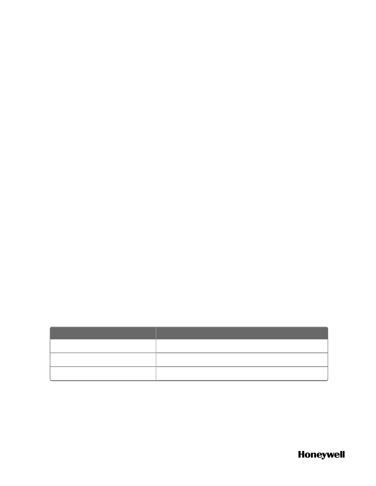
Table 5-16: UIO for Analog Output Specification
Item Description
Field (loop) resistance Minimal 100 ohm
D-A conversion 12 bit
Accuracy < 0.5% of full scale including linearity
Figure 5-27: Field wiring for analog output
116
 Loading...