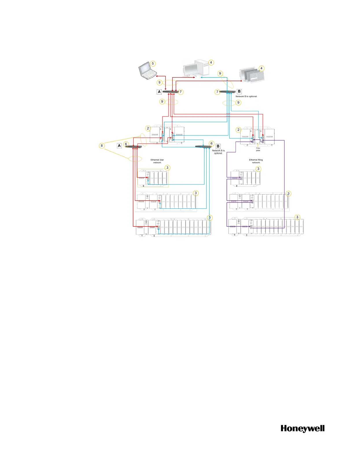
Figure 3-2: System architecture with redundant PLC-CPM
Physical cabling/connection of the nodes forming the ring, applicable
to the purple HSR/Ring topology on the right side of the above
illustration, must be connected as follows:
n CPM port 3 (ETH3) must be connected to CPM port 4 (ETH4) or
EPM port 2 (ETH2).
n CPM port 4 (ETH4) must be connected to CPM port 3 (ETH3) or
EPM port 1 (ETH1).
n EPM port 1 (ETH1) must be connected to EPM port 2 (ETH2) or
CPM port 4 (EHT4).
n EPM port 2 (ETH2) must be connected to EPM port 1 (ETH1) or
CPM port 3 (EHT3).
18
 Loading...